

Horizon 8 architecture
This chapter is one of a series that make up the Omnissa Workspace ONE and Horizon Reference Architecture, a framework that provides guidance on the architecture, design considerations, and deployment of Omnissa Workspace ONE and Omnissa Horizon solutions.
- This chapter provides information about architecting Omnissa Horizon 8.
- A companion chapter, Horizon 8 configuration, provides information about common configuration and deployment tasks for Horizon 8.
Introduction
Omnissa Horizon 8 manages and delivers virtualized or hosted desktops and applications to end users. Horizon allows you to create and broker connections to Windows virtual desktops, Linux virtual desktops, Remote Desktop Server (RDS)–hosted applications and desktops, Linux-hosted applications, and Windows physical machines.
This chapter of the reference architecture covers the architecture and design considerations for Omnissa Horizon 8. Horizon 8 can be deployed on-premises or on other supported cloud platforms. This chapter covers the foundational and common architectural information for deploying Horizon and is applicable across all supported platforms.
Separate chapters give the additional design considerations for Horizon 8 on supported cloud platforms, including VMware Cloud on AWS, Azure VMware Solution, Google Cloud VMware Engine, Oracle Cloud VMware Solution, and Alibaba Cloud VMware Service.
Table 1: Horizon 8 environment setup strategy
| Decision | A Horizon 8 deployment was designed, deployed, and integrated with the Workspace ONE platform. The environment was designed to be capable of scaling to 8,000 concurrent connections for users. |
| Justification | This strategy allowed the design, deployment, and integration to be validated and documented. |
Architectural overview
The core components of Horizon include a Horizon Client authenticating to a Connection Server, which brokers connections to virtual desktops and apps. The Horizon Client then forms a protocol session connection to a Horizon Agent running in a virtual desktop, RDSH server, or physical machine. The protocol session can also be configured to be tunneled via the Connection Server, although this is not generally recommended as it makes the ongoing session dependent on the Connection Server.
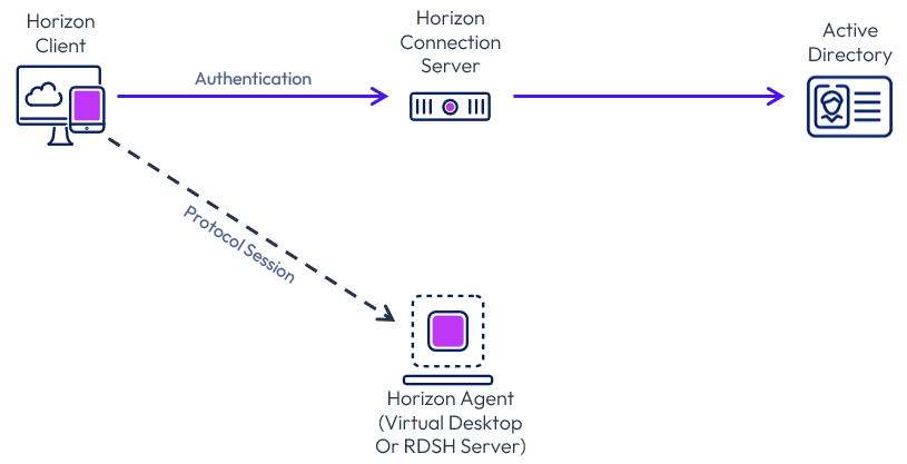
Figure 1: Horizon core components
External access includes the use of Unified Access Gateway to provide secure edge services. The Horizon Client authenticates to a Connection Server through the Unified Access Gateway. The Horizon Client then forms a protocol session connection, through the gateway service on the Unified Access Gateway, to a Horizon Agent running in a virtual desktop or RDSH server. This process is covered in more detail in External access.
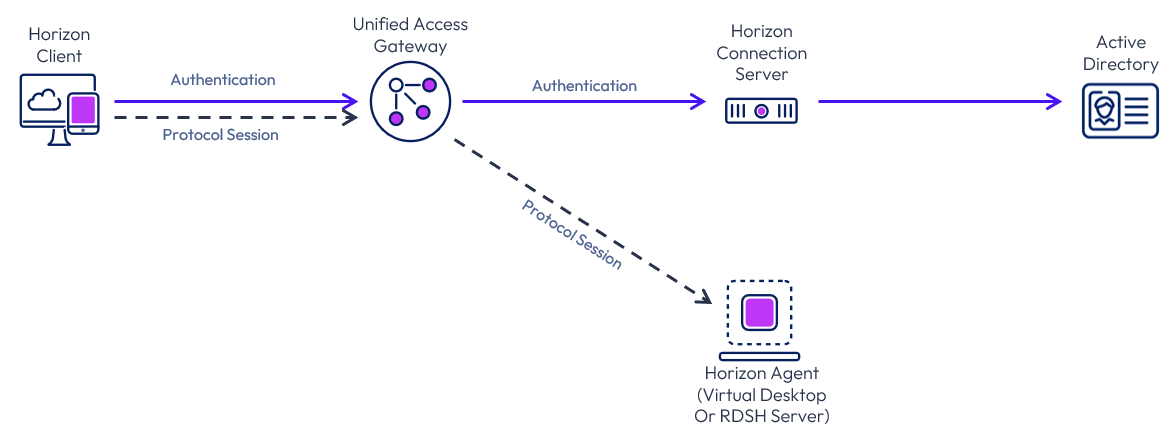
Figure 2: Horizon core components for external access
For more detail on how a Horizon connection is formed between the components, see Understand and troubleshoot Horizon connections.
Components
The following figure shows the high-level logical architecture of the Horizon components, with other Horizon components shown for illustrative purposes.
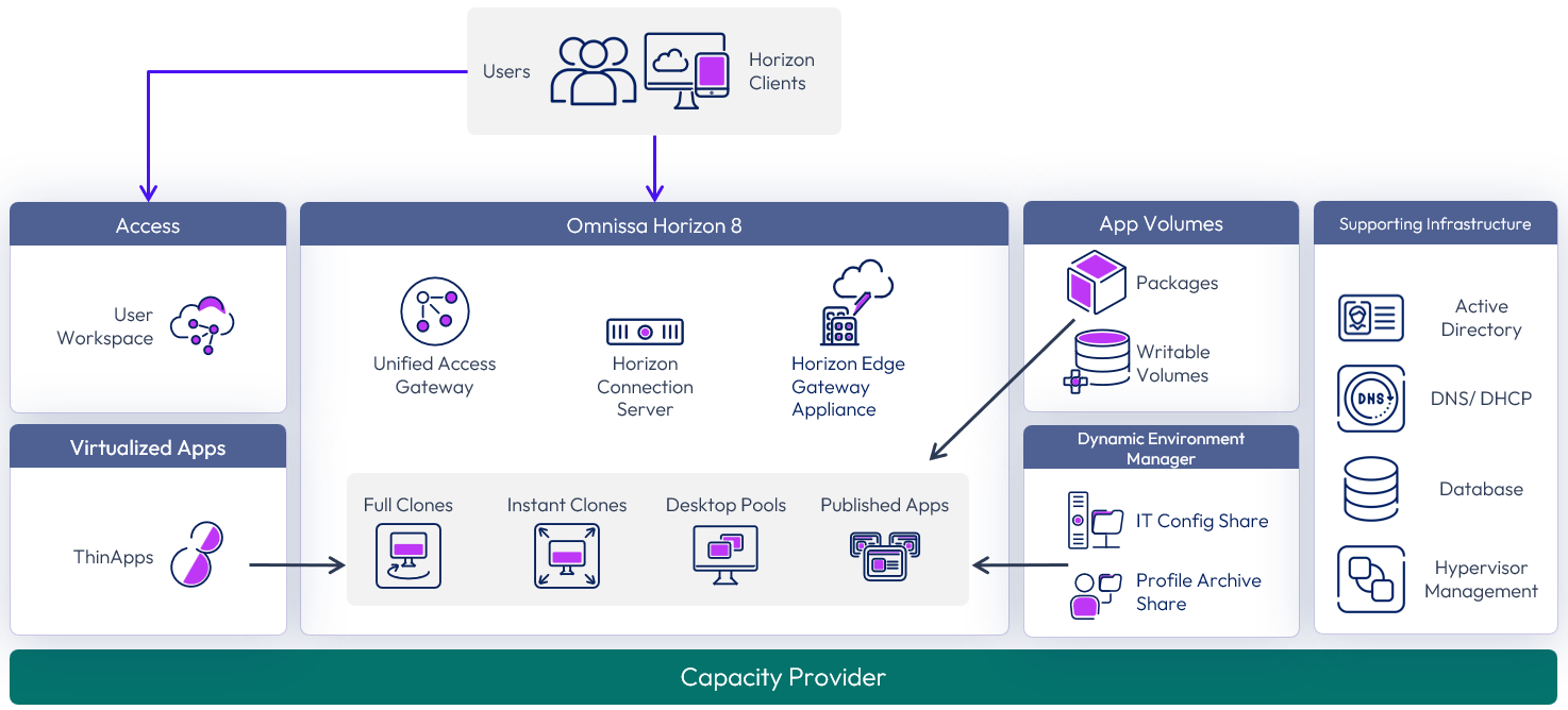
Figure 3: Horizon 8 logical components
The components and features of Horizon 8 are described in the following table.
Table 2: Components of Horizon 8
| Component | Description |
| Horizon Connection Server | The Horizon Connection Server securely brokers and connects users to the Horizon Agent that has been installed in the desktops and RDS Hosts. The Connection Server authenticates users through Active Directory and directs the request to the appropriate and entitled resource. |
| Horizon Agent | The Horizon Agent is installed on the guest OS of the target VM or system. This agent allows the machine to be managed by Connection Servers and allows a Horizon Client to form a protocol session to the machine. Machines can be virtual desktops, Remote Desktop Session Hosts (RDS Hosts), or physical desktops PCs. |
| Horizon Client | The Horizon Client is installed on a client device to access a Horizon-managed system that has the Horizon Agent installed. You can optionally use a web browser as an HTML client for devices on which installing client software is not possible. |
| Unified Access Gateway | Unified Access Gateway is a virtual appliance that enables secure remote access from an external network to a variety of internal resources, including Horizon-managed resources. When providing access to internal resources, Unified Access Gateway can be deployed within the corporate DMZ or internal network and acts as a reverse proxy host for connections to your company’s resources. Unified Access Gateway directs authenticated requests to the appropriate resource and discards any unauthenticated requests. It also can perform the authentication itself, leveraging an additional layer of authentication when enabled. For further information, see the External access section and the Unified Access Gateway Architecture guide for design and implementation details. |
| Horizon Enrollment Server | The Horizon Enrollment Server delivers True SSO functionality by ensuring a user can single-sign-on to a Horizon resource when launched from Omnissa Access, or through Unified Access Gateway, regardless of the authentication method. See the True SSO section for more information. |
| Horizon Edge Gateway appliance | The Horizon Edge Gateway is a virtual appliance that connects a Horizon 8 pod to Horizon Cloud Services. This is required when you want to use Horizon Cloud control plane services, for example, subscription licensing. For more information, see Horizon Edge Gateway appliance |
| Horizon Console | A web application that is part of the Connection Server, allowing administrators to configure the server, deploy and manage desktops, control user authentication, initiate and examine system and user events, carry out end-user support, and perform analytical activities. |
| Events Database | Horizon 8 uses an external database to record information about events.
For details on supported databases, see the Omnissa Interoperability Matrix. |
| RDSH servers | Microsoft Windows servers that provide published applications and session-based remote desktops to end users. |
| Clone technology | Technology that provides single-image management with automation capabilities. You can rapidly create automated pools or farms of instant-clone desktops or RDSH servers from a golden image VM. The technology reduces storage costs and streamlines desktop management by enabling easy updating and patching of hundreds or thousands of images from the golden image VM. |
From a data center perspective, several components and servers must be deployed to create a functioning Horizon 8 environment to deliver the desired services.
In addition to the core components and features, other products can be used in a Horizon 8 deployment to enhance and optimize the overall solution:
- App Volumes Manager – Orchestrates application delivery by managing assignments of application volumes (packages and writable volumes) to users, groups, and target computers. See App Volumes architecture for design and implementation details.
- Dynamic Environment Manager – Provides profile management by capturing user settings for the operating system and applications. See Dynamic Environment Manager architecture for design and implementation details.
- Omnissa Access – Provides enterprise single sign-on (SSO), securing and simplifying access to apps with the included identity provider or by integrating with existing identity providers. It provides application provisioning, a self-service catalog, conditional access controls, and SSO for SaaS, web, cloud, and native mobile applications. See Workspace ONE Access architecture for design and implementation details.
Scalability and availability
An important design goal should be to remove single points of failure in the deployment and to scale in a repeatable manner.
Note: The numbers, limits, and recommendations given in this section were correct at the time of writing. For the most current numbers for Horizon 8, see the Configuration Maximums.
Connection Server
A single Horizon Connection Server supports a maximum of 4,000 sessions. This is reduced to 2,000 sessions when tunneling connections through the Connection Server by using the Blast Secure Gateway, PCoIP Secure Gateway, or the HTTP(s) Secure Tunnel on the Connection Server.
Up to seven Connection Servers are supported per Horizon pod, with up to 20,000 active sessions in total per pod.
To satisfy the requirements that the proposed solution be robust and able to handle failure, deploy one more server than is required for the number of connections (n+1).
Table 3: Strategy for deploying Horizon Connection Servers
| Decision | Three Horizon Connection Servers were deployed per pod. These ran on dedicated Windows Server VMs located in the internal network. |
| Justification | One Connection Server supports up to 4,000 connections. Sessions are not tunneled through the Connection Servers and the secure gateways and secure tunnel are disabled on the Connection Servers. Two Connection Servers are required to handle the load of the target 8,000 users for each pod. A third server provides redundancy and availability (n+1). |
For more information, see Horizon 8 configuration.
Load balancing Connection Servers
For high availability and scalability, it is recommended that multiple Connection Servers be deployed in a load-balanced replication cluster. This ensures that user load is evenly distributed across all available servers and a single namespace can be used by end users. Using a load balancer also facilitates greater flexibility by enabling IT administrators to perform maintenance, upgrades, and configuration changes while minimizing impact to users.
Connection Servers broker client connections, authenticate users, and direct incoming requests to the correct agent resource. Although the Connection Server helps form the connection for authentication, it typically does not act as part of the data path after a protocol session has been established.
The load balancer serves as a central aggregation point for traffic flow between clients and Connection Servers, sending clients to the best-performing and most available Connection Server instance. To ensure that the load balancer itself does not become a point of failure, most load balancers allow for the setup of multiple nodes in an HA or active/passive configuration.
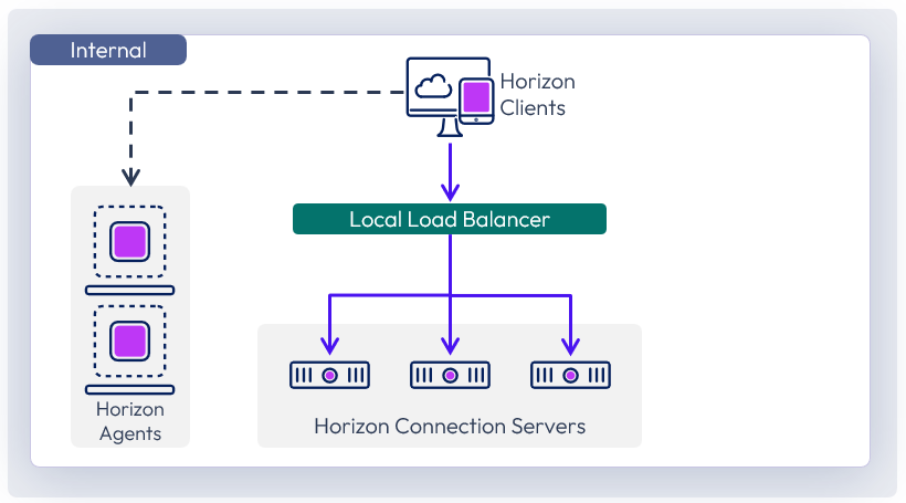
Figure 4: Connection Server load balancing
Connection Servers require the load balancer to have a session persistence setting. This is sometimes referred to as persistent connections or sticky connections, and ensures data stays directed to the relevant Connection Server. For more information, see the Knowledge Base article Load Balancing for Omnissa Horizon (2146312).
For details on timeout settings, health monitoring strings, and persistence values, see the Knowledge Base article Monitoring health of Horizon Connection Server using Load Balancer, timeout, Load Balancer persistence settings in Horizon 7.x and 8 (56636).
Table 4: Strategy for using load balancers with Connection Servers
| Decision | A load balancer was used in front of the Connection Servers for internal user connections. Source IP was configured for the persistence or affinity type. |
| Justification | This provides an internal common namespace for the Connection Servers, which allows for ease of use, scale, and redundancy. |
Pod and block
One key concept in a Horizon 8 environment design is the use of pods and blocks, which gives us a repeatable and scalable approach.
Pod
A pod is made up of a group of interconnected Connection Servers that broker connections to desktops or published applications.
- A pod can have up to seven Connection Servers.
- A pod can broker up to 20,000 sessions, including desktop and RDSH sessions.
- All Connection Servers in a single pod must be located within a single data center and cannot span locations.
- Multiple pods can be interconnected by using Cloud Pod Architecture (CPA).
- A single Cloud Pod Architecture can scale to a maximum of 250,000 sessions. For numbers above that, separate CPAs can be deployed.
Block
The resource capacity for a pod is provided by one or more resource blocks. Each block is made up of one or more resource clusters, and each block usually has its own hypervisor manager.
Resource blocks can be either in the same location as the Connection Servers or in a different location, using the Remote agents deployment model.
The number of virtual machines (VMs) a block can typically host depends on the type of Horizon VMs used and the hypervisor platform.
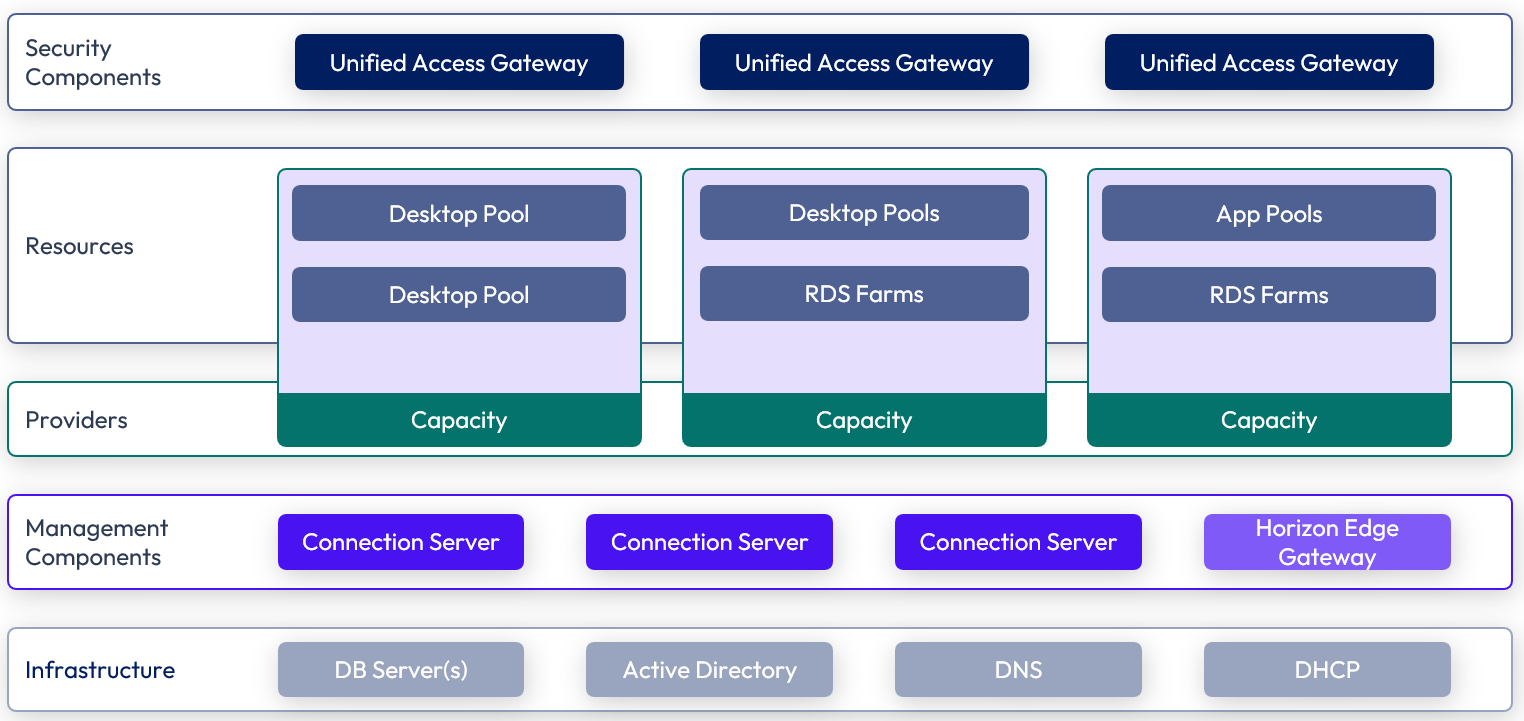
Figure 5: Horizon pod and block design
Hypervisor manager
The hypervisor manager is the delimiter of a single resource block. Different hypervisor managers have different maximums and recommendations for number of VMs that they support. For information on specific hypervisor resource blocks, see:
Just because configuration maximums are published does not mean you should necessarily design to that limit. Using a single hypervisor manager might introduce a single point of failure that could affect too large a percentage of the VMs in your environment. Therefore, carefully consider the size of the failure domain and the impact should that hypervisor manager become unavailable. A single manager might be capable of supporting your whole environment, but to reduce risk and minimize the impact of an outage, you will probably want to include more than one in your design.
Sizing can also have performance implications because a single management server could become a bottleneck if too many provisioning tasks run at the same time. Do not just size for normal operations but also understand the impact of provisioning tasks and their frequency.
You can increase the availability of the hypervisor manager, and other Horizon management VMs, by using hypervisor high availability (HA), which restarts the VM in the case of a host outage.
Scaling with pod and block
To add more resource capacity, we simply add more resource blocks. We also add more Connection Servers to add the capability for more session connections within the pod.
Depending on the types of VMs, (type of clones, and if using App Volumes), a resource block could host a different number of VMs. Typically, we have multiple resource blocks and up to seven Connection Servers in a pod capable of hosting up to 20,000 sessions. For numbers above that, we deploy additional pods.
As you can see, this approach allows us to design a single block capable of thousands of sessions that can then be repeated to create a pod capable of handling 20,000 sessions. Multiple pods grouped to scale the environment as large as required, using Cloud Pod Architecture.
Co-hosting management and end user resources
In large environments, for scalability and operational efficiency, it is normally best practice to have a separate resource cluster to host the Horizon 8 management components. This keeps the VMs that run services such as Connection Server, Unified Access Gateway, App Volumes managers, and databases separate from the desktop and RDSH server VMs.
In smaller deployments or where the use of converged hardware is used and the cost of providing dedicated hosts for management is too high, one option is to co-hosted the Horizon 8 management components and the end-user resources, such as virtual desktops, on the same cluster and using the same hypervisor manager.
Options regarding the location of management components, such as Connection Servers, include:
- Co-located on the same hypervisor hosts as the desktops and RDSH servers that will serve end-users
- On a separate hypervisor cluster
- On separate cloud compute resources, in line with the recommendations of the given cloud platform
If you place everything on the same cluster, you should ensure resource prioritization for the Horizon 8 management components. The sizing of resources (for example, virtual desktops) must also take into account the overhead of the management servers.
Table 5: Pod and block design for this reference architecture
| Decision | A Horizon 8 pod was deployed in each site. Each pod contained one or more resource blocks. |
| Justification | Deploying multiple, separate pods in different sites provides site redundancy and allows an equivalent service to be delivered to the user from an alternate location. This allowed the design and deployment of the block and pod architecture to be validated and documented. |
Cloud Pod Architecture
When multiple Horizon pods are being deployed, you can use Cloud Pod Architecture (CPA). This allows multiple Horizon pods to be joined together into a federation and then global entitlements (GE) to be assigned that include entitlements from multiple pods. Participating pods can be located in the same physical site or location or in different sites and locations.
This allows you to provide users and groups with a global entitlement that can contain desktop pools or RDSH-published applications from multiple different pods that are members of this federation construct.
The following figure shows a logical overview of a basic two-pod CPA implementation.
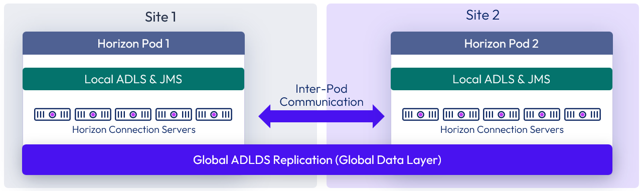
Figure 6: Cloud Pod Architecture
For the full documentation on how to set up and configure CPA, refer to Cloud Pod Architecture in Horizon 8.
Important: This type of deployment is not a stretched deployment. Each pod is distinct, and all Connection Servers belong to a specific pod and are required to reside in a single location and run on the same broadcast domain from a network perspective.
As well as being able to have desktop pool members or published applications from different pods in a global entitlement, this architecture allows for a property called scope. Scope allows us to define where new sessions should or could be placed and also allows users to connect to existing sessions (that are in a disconnected state) when connecting to any of the pod members in the federation.
CPA can also be used within a site:
- To use global entitlements that span multiple resource blocks and pools
- To federate multiple pods on the same site, when scaling above the capabilities of a single pod
External access
Secure, external access for users accessing resources is provided through the integration of Omnissa Unified Access Gateway (UAG) appliances. A Unified Access Gateway appliance can be used in front of Connection Servers to provide access to Horizon desktops and published applications. This encrypts and secures Horizon user sessions and eliminates the need for a separate VPN infrastructure.
When deploying multiple Unified Access Gateway appliances to provide scalability and allow for redundancy, either the built-in high availability or a third-part load balancer can be used to present a virtual IP address and present users with a single namespace.
External access architecture
When using Unified Access Gateway to provide external access to Horizon, the same Connection Servers can be used for both external and internal connections.
With the preferred architecture for traffic flow and load balancing of Unified Access Gateways and Connection Servers, a load balancer is not placed in-line between the Unified Access Gateways and the Connection Servers. This architecture simplifies the design and makes it easier to troubleshoot. An individual Unified Access Gateway can detect if its target Connection Server is not responding and will notify the external load balancer that it can no longer handle any new connections.
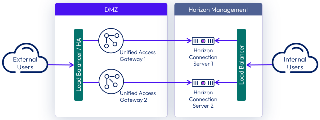
Figure 7: Unified Access Gateway and Connection Server architecture
While the previous diagram shows a 1-to-1 mapping of Unified Access Gateway to the Connection Server, it is also possible to have a N-to-1 mapping, where more than one Unified Access Gateway maps to the same Connection Server.
High availability and resilience are maintained by having at least two Unified Access Gateways and ensuring that they specify different Connection Servers as targets for the Connection Server URL.
Note: It is still a valid architecture and supported to have a load balancer inline between the Unified Access Gateways and the Connection Servers. However, when a load balancer is placed between the two, the Unified Access Gateway cannot detect if an individual Connection Server is down.
When required for internally routed connections, a load balancer for the Connection Servers can be either:
- Located so that only internal users use it as an FQDN.
- Placed in between the Unified Access Gateways and the Connection Server and used as an FQDN target for both internal users and the Unified Access Gateways.
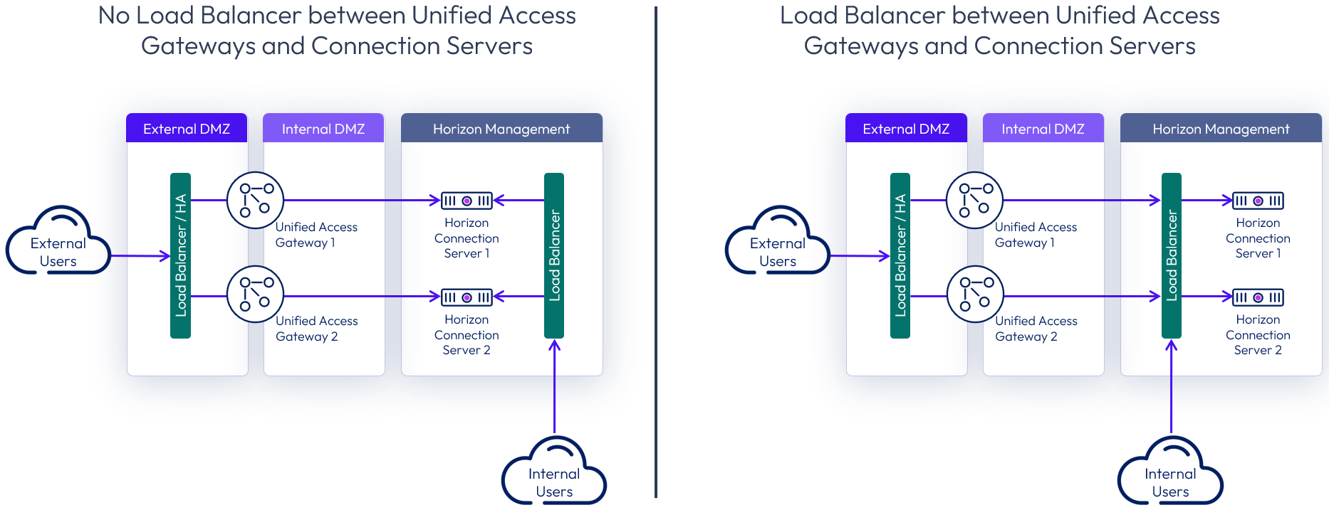
Figure 8: Options for load balancing Connection Servers for internal connections
Single DMZ
For on-premises deployment of Horizon within a data center of an organization, it is common to install Unified Access Gateway appliances in a single DMZ, which provides a network isolation layer between the Internet and the customer data center.
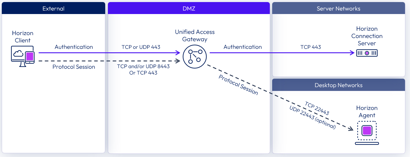
Figure 9: Single DMZ deployment showing Blast ports
Unified Access Gateway has built-in security mechanisms for all the Horizon protocols to ensure that the only network traffic entering the data center is traffic on behalf of an authenticated user. Any unauthenticated traffic is discarded in the DMZ.
Double DMZ
Some organizations have two DMZs (often called a double DMZ or a double-hop DMZ) that are sometimes used to provide an extra layer of security protection between the Internet and the internal network. In a double DMZ, traffic has to be passed through a specific reverse proxy in each DMZ layer. Traffic cannot simply bypass a DMZ layer.
Note that in a Horizon deployment, a double DMZ is not required, but for environments where a double DMZ is mandated, an extra Unified Access Gateway appliance acting as a Web Reverse Proxy can be deployed in the outer DMZ.
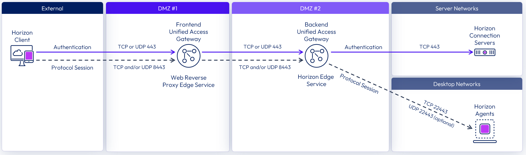
Figure 10: Double DMZ deployment showing Blast protocol ports
For more information, see Unified Access Gateway Double DMZ Deployment for Horizon.
Unified Access Gateway scaling
When deployed for Horizon Edge services you have a choice of which size Unified Access Gateway appliances to deploy. See Unified Access Gateway sizing options for VM resource allocations.
- A standard-sized Unified Access Gateway appliance is typically deployed to support up to 2,000 Horizon sessions per appliance.
- Beginning with the 2512 release, the extra-large size of the Unified Access Gateway appliance can be deployed, which can support up to 4,000 Horizon sessions each.
When designing Unified Access Gateway appliance numbers, a balance with the number of Connection Servers should be considered to ensure that overall availability is maintained in the event of failure of either server component.
For information on scaling and the design of Unified Access Gateway, see Unified Access Gateway architecture.
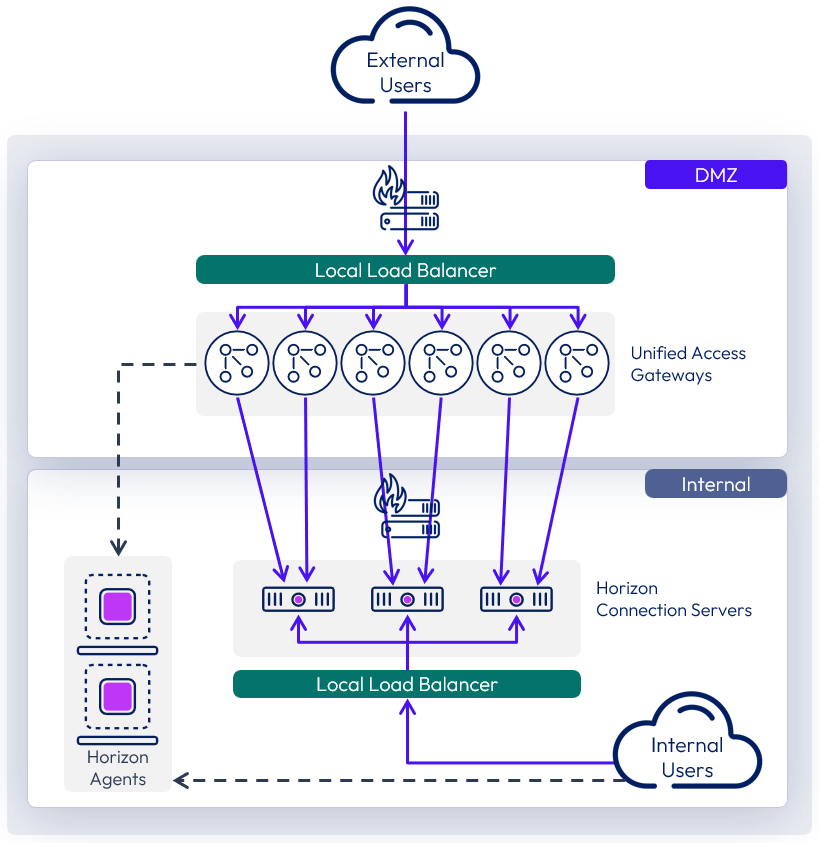
Figure 11: Scaling out Unified Access Gateways
Table 6: Implementation strategy for external access
| Decision | Six standard-size Unified Access Gateway appliances were deployed as part of the Horizon solution. These were located in the DMZ network. |
| Justification | UAG provides secure external access to internally hosted Horizon desktops and applications. One standard-size UAG appliance is recommended for up to 2,000 concurrent Horizon connections. Four UAG appliances are required to handle the load of the target 8,000 users. We elected not to place a load balancer in-line between the UAGs and the Connection Server, so each UAG targets a particular Connection Server. To match up with the sizing requirement for three Connection Servers, we should look to have a 2-to-1 ratio of UAG to Connection Server. This leads to an overall count of six UAGs, to ensure redundancy and availability. |
Load balancing Unified Access Gateway
It is strongly recommended that end users connect to Unified Access Gateway using a load-balanced virtual IP (VIP). This ensures that user load is evenly distributed across all available Unified Access Gateway appliances and facilitates greater flexibility by enabling IT administrators to perform maintenance, upgrades, and configuration changes while minimizing impact to users.
To implement them in a highly available configuration, provide a virtual IP address (VIP), and present users with a single namespace, the following options can be used.
- A third-party load balancer can be used.
- Unified Access Gateway high availability (HA) can be used.
When load balancing Horizon traffic to multiple Unified Access Gateway appliances, the initial XML-API connection (authentication, authorization, and session management) needs to be load balanced. The secondary Horizon protocols must be routed to the same Unified Access Gateway appliance to which the primary Horizon XML-API protocol was routed. This allows the Unified Access Gateway to authorize the secondary protocols based on the authenticated user session.
If the secondary protocol session is misrouted to a different Unified Access Gateway appliance from the primary protocol one, the session will not be authorized. The connection would therefore be dropped in the DMZ, and the protocol connection would fail. Misrouting secondary protocol sessions is a common problem if the load balancer is not configured correctly.
The load balancer affinity must ensure that XML-API connections made for the whole duration of a session (with a default maximum of 10 hours) continue to be routed to the same Unified Access Gateway appliance.
With the use case of providing secure, external access to resources, there is no need to provide a single namespace to the Horizon Connection Servers because only external users will be connecting. This means that there is no need to provide a load balancer VIP in front of the Connection Servers.
Although the secondary protocol session must be routed to the same Unified Access Gateway appliance as was used for the primary XML-API connection, there is a choice of whether the secondary protocol session is routed through the load balancer or not. This normally depends on the capabilities of the load balancer.
For more details on load balancing of Unified Access Gateway appliances, see:
- Load Balancing in the Unified Access Manager Architecture chapter
- Load Balancing Topologies
- Load Balancing Unified Access Gateway for Horizon
Table 7: Strategy for using load balancers with Unified Access Gateways
| Decision | For the on-premises deployments of Horizon, a load balancer was used in front of Unified Access Gateways. Source IP was configured for the persistence or affinity type. |
| Justification | This provides a common namespace for the Unified Access Gateways, which allows for ease of use, scale, and redundancy. |
Unified Access Gateway high availability
As an alternative to using a third-party load balancer, Unified Access Gateway provides, out-of-the-box, a high-availability solution for the Unified Access Gateway edge services. The solution supports up to 10,000 concurrent connections in a high-availability (HA) cluster and simplifies HA deployment and configuration of the services.
For more information on the Unified Access Gateway High Availability component and configuration of edge services in HA, see the following resources:
- High Availability section of Unified Access Gateway architecture
Networking
To ensure correct communication between the components, it is important to understand the network port requirements for connectivity in a Horizon deployment. The Network Ports in Horizon 8 guide has more detail and includes diagrams illustrating the traffic. It has specific sections and diagrams on internal, external, and tunneled connections.
Notes:
- The network ports shown are destination ports.
- The arrows indicate the direction of traffic initiation (source to destination).
- Horizon UDP protocols are bidirectional, so stateful firewalls should be configured to accept UDP reply datagrams.
For further information on Horizon sessions and traffic flows, see Understand and Troubleshoot Horizon Connections.
Display protocol
Horizon is a multi-protocol solution. Three remoting protocols are available when creating desktop pools or RDSH-published applications: Blast, PCoIP, and RDP.
Table 8: Display protocol for virtual desktops and RDSH-published apps
| Decision | For this design, we leveraged Blast. |
| Justification | This display protocol supports multiple codecs, both TCP and UDP from a transport protocol perspective, and the ability to do hardware encoding with NVIDIA GRID vGPU. |
Blast is configured through Horizon when creating a pool. The display protocol can also be selected directly on the Horizon Client side when a user selects a desktop pool or published application.
See the following guides for more information, including optimization tips:
Internal connections
With internal connections, the Horizon Client authenticates to a Connection Server, which brokers connections to Horizon desktops and published apps. The Horizon Client then forms a protocol session connection to a Horizon Agent running in a virtual desktop, RDSH server, or physical machine.
The following diagram shows the ports required to allow an internal Blast connection.
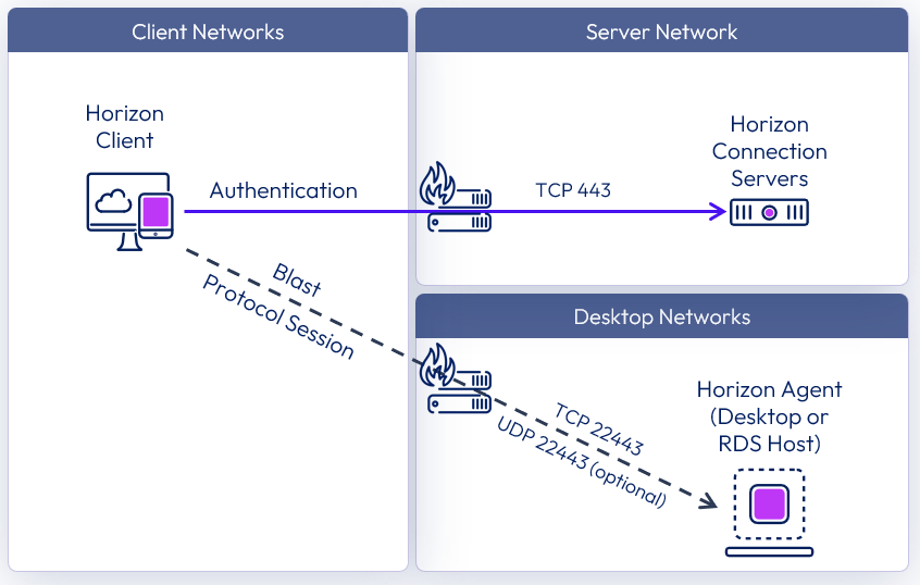
Figure 12: Internal connection with Blast network ports
The following diagram shows the ports required to allow an internal PCoIP connection.
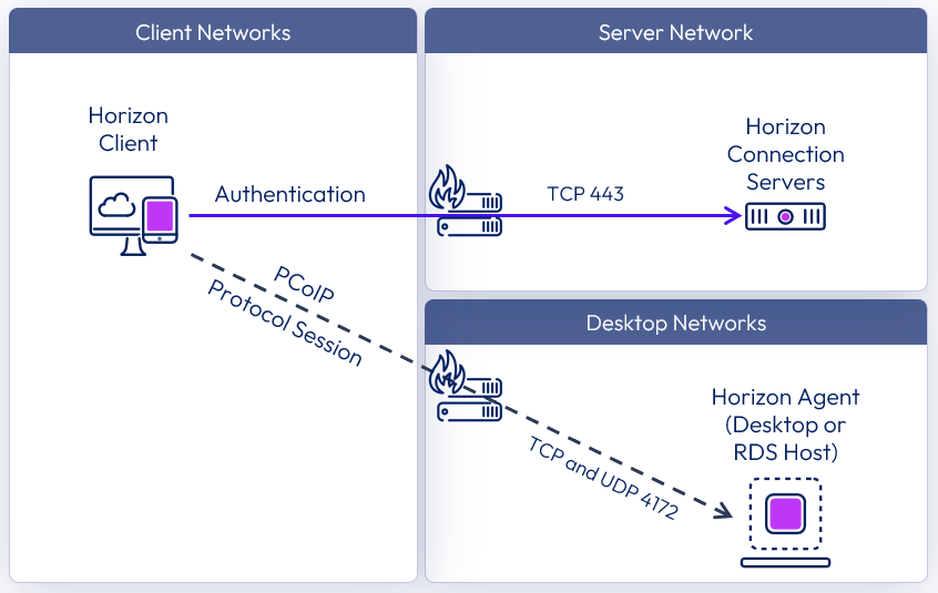
Figure 13: Internal connection with PCoIP network ports
The following diagram shows the ports required to allow an internal RDP connection.

Figure 14: Internal connection with RDP network ports
External connections
External connections include the use of Unified Access Gateway to provide secure edge services. The Horizon Client authenticates to a Connection Server through the Unified Access Gateway. The Horizon Client then forms a protocol session connection, through the secure gateway service on the Unified Access Gateway, to a Horizon Agent running in virtual desktop, RDSH server, or physical machine.
The following diagram shows the ports required to allow an external Blast connection.
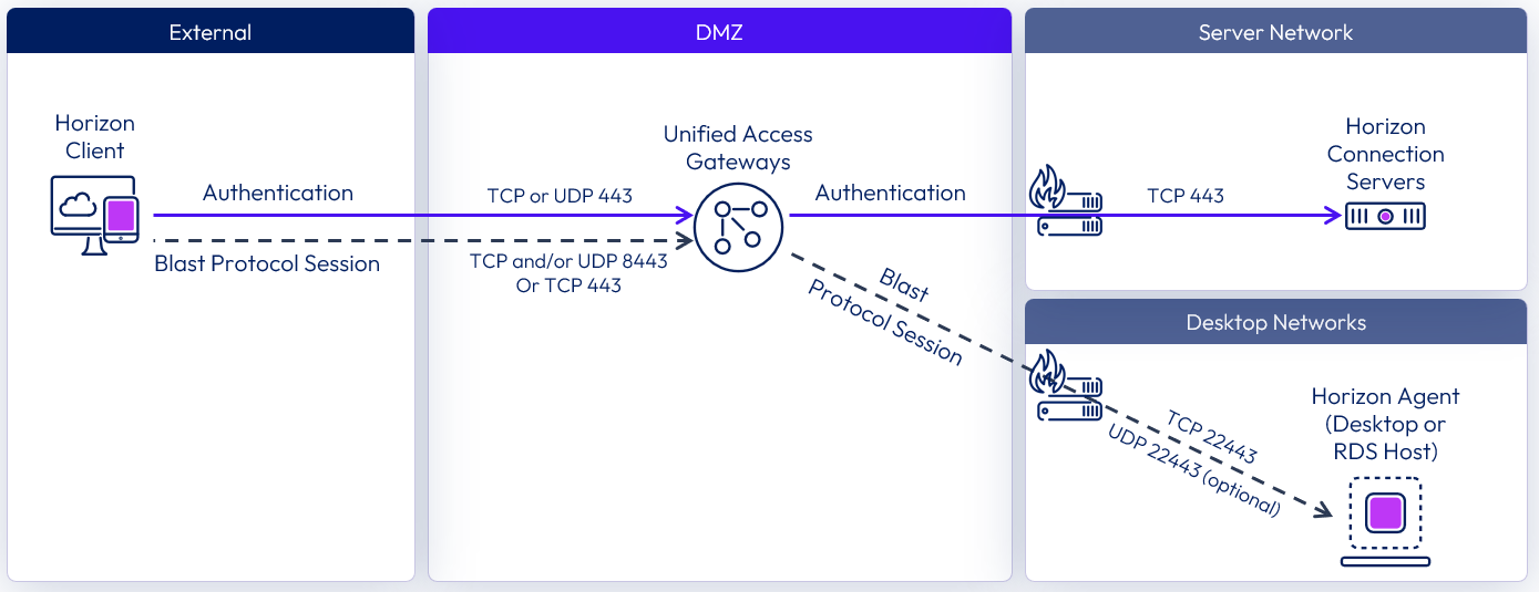
Figure 15: External connection with Blast network ports
The following diagram shows the ports required to allow an external PCoIP connection.

Figure 16: External connection with PCoIP network ports
The following diagram shows the ports required to allow an external RDP connection.
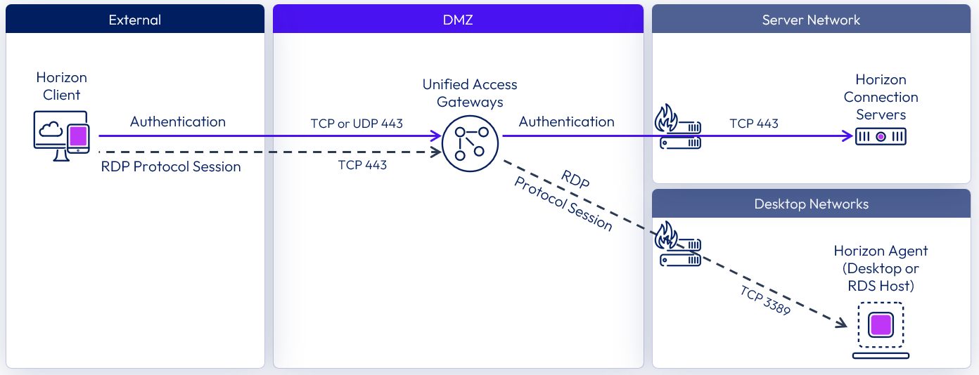
Figure 17: External connection with RDP network ports
Micro-segmentation
Micro-segmentation takes the concept of network segmentation, typically done with physical devices such as routers, switches, and firewalls at the data center level, and provides the ability to insert a security policy into the access layer between any two workloads in the same extended data center.
Micro-segmentation technologies enable the definition of fine-grained network zones, down to individual VMs and applications. This can be used to provide a network-least-privilege security model for traffic between workloads within the data center.
Although optional in a Horizon 8 deployment, micro-segmentation can provide several security functions, when required:
- Isolate desktop pool VM communication – Apply policy to block or limit desktop to desktop, or pool to pool communication.
- Protects Horizon 8 management infrastructure – Secure communication to and among the management components of a Horizon 8 infrastructure.
- Enhance Enterprise Application Security - Assist in securing and limiting access to applications inside the data center from Horizon desktops.
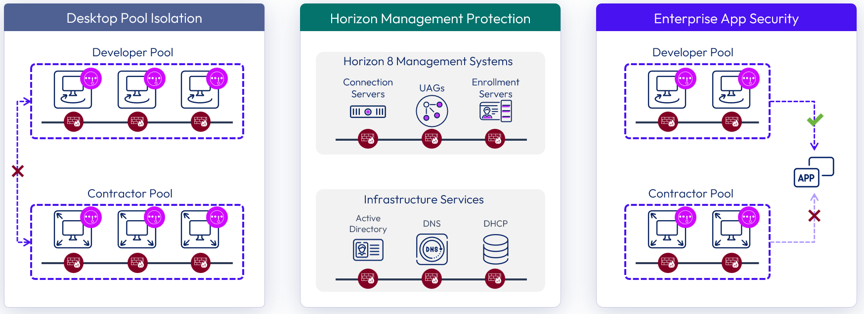
Figure 18: Micro-segmentation use cases for Horizon 8
For more information, and a list with reviews, on different vendors who provide micro-segmentation products, see the Gartner page on Microsegmentation Reviews and Ratings.
Table 9: Strategy for Micro-segmentation
| Decision | Micro-segmentation was not deployed. |
| Justification | Standard network segmentation, VLANs, and firewalls provided the necessary level of isolation and traffic filtering required for the environments being deployed. |
Horizon Control Plane
To enable the use of Horizon Plane services, such as SaaS subscription licensing, Universal Broker, Image Management Service (IMS), and monitoring with Omnissa Intelligence for Horizon, the Horizon 8 pod has to be connected to the Horizon Control Plane.
- A Horizon Edge Gateway appliance is used to connect a Horizon 8 pod to Horizon Control Plane.
- For more information on Horizon Cloud and Horizon Control Plane services, see Horizon Cloud architecture.
Table 10: Strategy for Horizon Control Plane connectivity
| Decision | The Horizon 8 pods were connected to the Horizon Control Plane. One Horizon Edge Gateway appliance was deployed per Horizon 8 pod. |
| Justification | Connecting the Horizon 8 pods to the Horizon Control Plane allows the option to consume cloud services, including enabling subscription licensing. |
Horizon Edge Gateway appliance
The Horizon Edge Gateway is a virtual appliance that is used to connect a Horizon 8 pod with the Horizon Control Plane and features. A separate Horizon Edge Gateway is required for each Horizon 8 pod that you connect to the Horizon Control Plane.
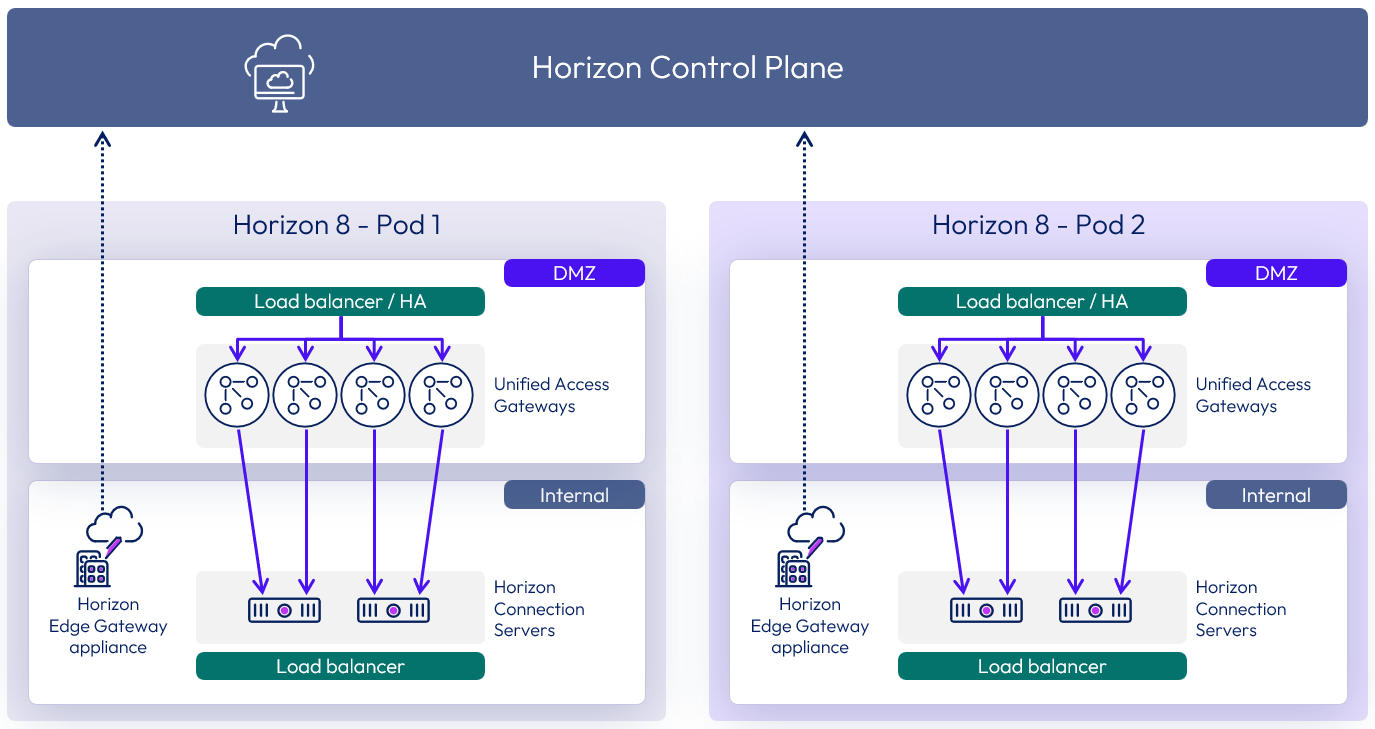
Figure 19: Horizon 8 Pods connected to the Horizon Control Plane with Horizon Edge Gateway appliances
For instructions on deploying Horizon Edge Gateway Appliances to connect a Horizon 8 pod to the Horizon Control Plane, see the Deploying a Horizon Edge Gateway for Horizon 8 environments guide.
The documentation also has several resources to assist in the Horizon Edge Gateway appliance deployment:
Hypervisor VM-level high availability (HA) can be used to restart Horizon Edge Gateway appliances in the event of a hypervisor host failure.
To understand the network communication and port requirements for the Horizon Edge Gateway appliance, see Network Ports in Horizon 8.
Horizon Cloud entitlement on-ramp
Horizon Cloud Entitlement On-Ramp is a feature for Horizon 8 end-users that enables the Horizon Client to display list of entitlements gathered from both a Horizon 8 deployment and a Horizon Cloud implementation. The resultant list of entitlements for all platforms is displayed in a single UI for users to select from.
This feature is intended for environments that need to burst to native Microsoft Azure based capacity with minimal change to end-users. This does not impact the use of Global Entitlements from multiple Horizon 8 pod deployments leveraging Cloud Pod Architecture.
Setup and configuration of the Horizon Cloud Entitlement On-Ramp feature is very straightforward.
- Setup prerequisites outlined in Enabling Horizon Cloud Entitlement On-Ramp to Access User Desktops
- Enable Horizon Cloud Entitlement On-Ramp in the Horizon Universal Console
- Enable Horizon Cloud Entitlement On-Ramp in the Horizon 8 Administrator Console and enable user groups for access to the feature.
After completing those configuration items, users will begin to see entitlements for their Horizon 8 and Horizon Cloud environments in the same Horizon Client UI upon their next login to the Horizon 8 pod.
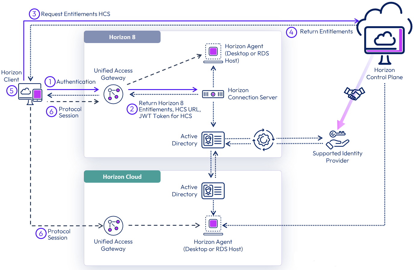
Figure 20: On-Ramp login and entitlement lookup
Horizon Cloud entitlement on-ramp modifies some aspects of a user’s login process. The updated process is as follows:
- A user launches their Horizon Client and authenticates to a Horizon 8 Connection Server.
- The user’s Horizon 8 entitlements are returned to the client, along with a short-lived JSON web token.
- The Horizon Client takes the token and presents it to Horizon Cloud. That token authorizes the client to look up that user’s entitlements.
- Horizon Cloud returns the user’s entitlements from all Horizon Cloud deployments.
- The user is presented a list of all of their entitlements in each system and makes a selection. In the example pictured above, a Horizon Cloud based resource is selected.
- The user’s protocol session starts as normal.
Note: Since both environments are connected to the Horizon Cloud service, and are using the same directory of record, the service is using the Horizon 8 Connection server as an Identity Provider to authorize the user to lookup entitlements on Horizon Cloud.
Note: The brokering experience for Horizon 8 and Horizon Cloud does not change with this new feature, only the user resource selection within the Horizon Client changes.
Authentication
There are a variety of methods for authenticating users in Horizon 8 to control access to desktops and published applications.
Omnissa Access authentication
One of the methods of accessing Horizon desktops and applications is through Omnissa Access. This requires integration between Horizon Connection Servers and Access using the SAML 2.0 standard to establish mutual trust, which is essential for single sign-on (SSO) functionality.
When SSO is enabled, users who log in to Access with Active Directory credentials can launch remote desktops and applications without having to go through a second login procedure. If you set up the True SSO feature, users can log in using authentication mechanisms other than AD credentials. See Using SAML Authentication and see Setting Up True SSO.
When defining the SAML authenticator on the Connection Servers, you can choose to set the delegation of authentication to allowed or required.
- Allowed makes this optional.
- Required enforces the use of the SAML authentication source.
- When configured as required you can also enable Workspace ONE mode which redirects any direct authentication attempts into Access.
See Configure Workspace ONE Access Policies in Horizon Console.
For details on Horizon and Workspace ONE Access Integration see the Component integration chapter.
Table 11: Strategy for authenticating users through Omnissa Access
| Decision | A SAML authenticator for Access was configured to be required on the Connection Servers. Workspace ONE mode was enabled on the Connection Servers. |
| Justification | With this configuration, Connection Servers allow Omnissa Access to be a dynamic SAML authenticator. This strategy facilitates the launch of Horizon resources only from Access and redirects any attempts to authenticate directly to Horizon back to Access. |
Unified Access Gateway authentication
Omnissa Unified Access Gateway supports multiple authentication options; for example, pass-through, RSA SecurID, RADIUS, SAML, and certificates, including smart cards. Pass-through authentication forwards the request to the internal server or resource. Other authentication types enable authentication at the Unified Access Gateway, before passing authenticated traffic through to the internal resource.
You can also use SAML to authenticate Horizon users against a third-party identity provider (IdP), leveraging Unified Access Gateway as the service provider (SP).
See Authentication options in Unified Access Gateway Architecture.
Table 12: Strategy for authenticating users through Unified Access Gateway
| Decision | Unified Access Gateway was left with the default pass-through authentication and no additional authentication methods were implemented on Unified Access Gateway. |
| Justification | This configuration facilitates the launch of Horizon resources from Access and will use that as the user authentication point. Implementing further authentication on the Unified Access Gateway would force users to have to authenticate twice. |
True SSO
Many user authentication options are available for users logging into Horizon including using Omnissa Access or Unified Access Gateway. Active Directory credentials are only one of these many authentication options. Ordinarily, using anything other than AD credentials would prevent a user from being able to single-sign-on to a Horizon virtual desktop or published application. After selecting the desktop or published application from the catalog, the user would be prompted to authenticate again, this time with AD credentials.
True SSO provides users with SSO to Horizon desktops and applications regardless of the authentication mechanism used. If a user authenticates by using Active Directory credentials, the True SSO feature is not necessary, but you can configure True SSO to be used even in this case so that the AD credentials that the user provides are ignored and True SSO is used.
True SSO uses SAML, where Workspace ONE is the Identity Provider (IdP) and the Horizon Connection Server is the Service Provider (SP). True SSO generates unique, short-lived certificates to manage the login process.
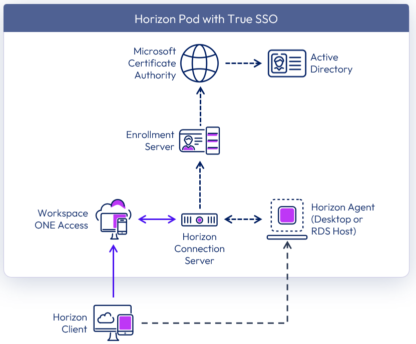
Figure 21: True SSO logical architecture
Table 13: Implementation strategy for SSO
| Decision | True SSO was configured and enabled. |
| Justification | This feature allows SSO to Horizon resources when launched from Omnissa Access, even when the user does not authenticate with Active Directory credentials. |
True SSO requires the Horizon Enrollment Server service to be installed using the Horizon installation media.
True SSO components
For True SSO to function, several components must be installed and configured within the environment. This section discusses the design options and details the design decisions that satisfy the requirements.
Note: For more information on how to install and configure True SSO, see Setting Up True SSO in the Horizon Administration documentation and the Setting Up True SSO section in Horizon 8 configuration.
The Horizon Enrollment Server is responsible for receiving certificate signing requests (CSRs) from the Connection Server. The enrolment server then passes the CSRs to the Microsoft Certificate Authority to sign using the relevant certificate template. The Enrollment Server is a lightweight service that can be installed on a dedicated Windows Server instance, or it can co-exist with the MS Certificate Authority service. It cannot be co-located on a Connection Server.
The components of Horizon True SSO are described in the following table.
Table 14: Components of Horizon True SSO
| Component | Description |
| Enrollment Server | A server that delivers True SSO functionality by ensuring a user can single-sign-on to a Horizon resource when launched from Omnissa Access, regardless of the authentication method. The Enrollment Server is responsible for receiving certificate signing requests from the Connection Server and then passing them to the Certificate Authority to sign. True SSO requires Microsoft Certificate Authority services, which it uses to generate unique, short-lived certificates to manage the login process. |
| Certificate Authority | Active Directory Certificate Services (AD CS) role running on a Windows server. |
| Certificate Template | Used for issuing short-lived certificates that are used as part of the SSO process. |
Load balancing of Enrollment Servers
Two Enrollment Servers were deployed in the environment, and the Connection Servers were configured to communicate with both deployed Enrollment Servers. The Enrollment Servers can be configured to communicate with two Certificate Authorities.
By default, the Enrollment Servers use an Active/Failover method of load balancing. It is recommended to change this to round-robin when configuring two Enrollment Servers per pod to achieve high availability.
Table 15: Strategy for load balancing between the enrollment Servers
| Decision | The Connection Servers were configured to load balance requests using round robin between the two Enrollment Servers. |
| Justification | With two Enrollment Servers per pod, this is the recommendation when designing for availability. |
Hypervisor high availability (HA) can be used to ensure the maximum availability of the Enrollment Servers. Anti-affinity rules should be configured to ensure that the individual enrollment servers do not reside on the same hypervisor host.
True SSO scalability
A single Enrollment Server can handle all the requests from a single Horizon pod. The constraining factor is usually the Certificate Authority (CA). A single CA can generate approximately 35 certificates per second.
To ensure availability, a second Enrollment Server should be deployed per pod (n+1). Additionally, ensure that the certificate authority service is deployed in a highly available manner, to ensure complete solution redundancy.
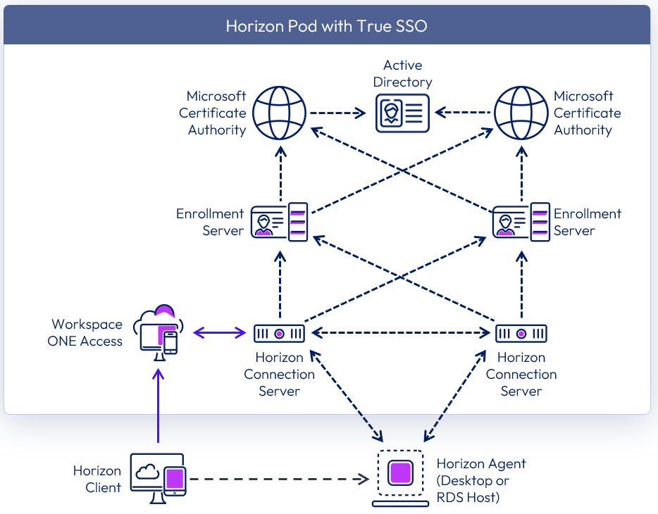
Figure 22: True SSO high availability
With two Enrollment Servers, and to achieve high availability, it is recommended to:
- Co-host the Enrollment Server service with a Certificate Authority service on the same machine.
- Configure the Enrollment Server to prefer to use the local Certificate Authority service.
- Configure the Connection Servers to load-balance requests between the two Enrollment Servers.
Table 16: Implementation strategy for Enrollment Servers
| Decision | Two Enrollment Servers were deployed per Pod. These ran on dedicated Windows Server VMs located in the internal network. These servers also had the Microsoft Certificate Authority service installed. |
| Justification | One Enrollment Server is capable of supporting a pod of 20,000 sessions. A second server provides availability (n+1). |
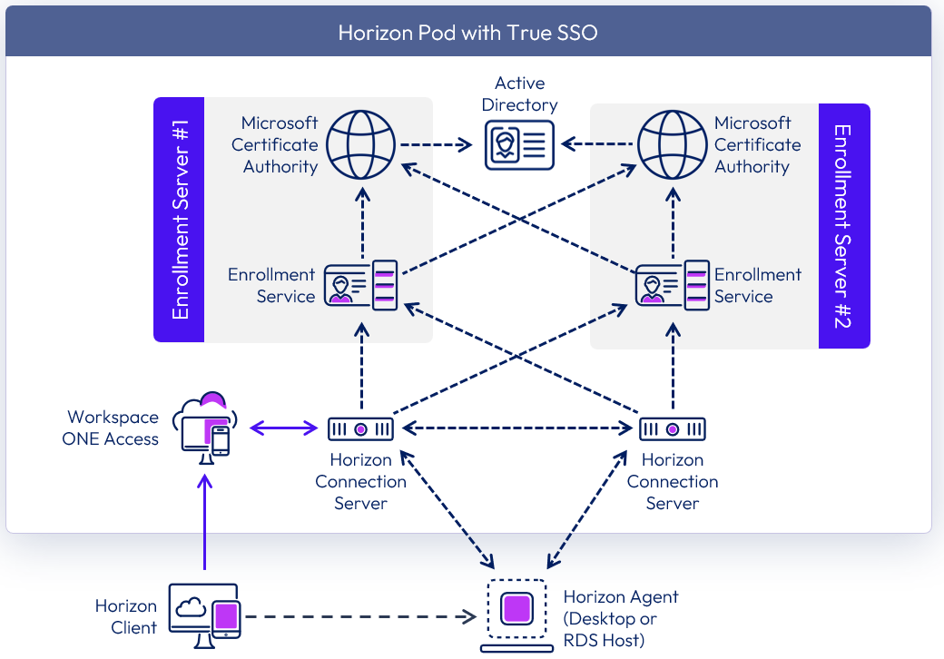
Figure 23: True SSO high availability co-located
Active Directory domains
True SSO is supported in both single-domain and in multi-domain environments. With multiple domains, two-way trusts should be in place between the domains.
Looking at an example with two active directory domain trees (A & X) that are in the same active directory forest. Each of the domain trees has transitive trusts between all domains in that tree. Additionally, domain A tree and domain X tree have a two-way, transitive trust relationship between each other.
True SSO is supported in this scenario, and the Enrollment Servers can be placed in any domain.
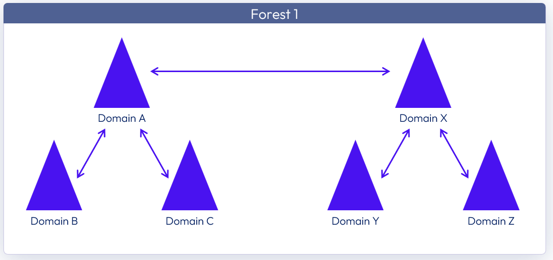
Figure 24: Two domain trees in the same forest
Looking at another example with two active directory forests each containing its own active directory domain trees. In each of the forests, each of the domain trees has transitive trusts between all domains in the tree. Additionally, the two forests have a two-way, forest-level trust in place.
The Enrollment Servers can be placed within any domain of any forest.
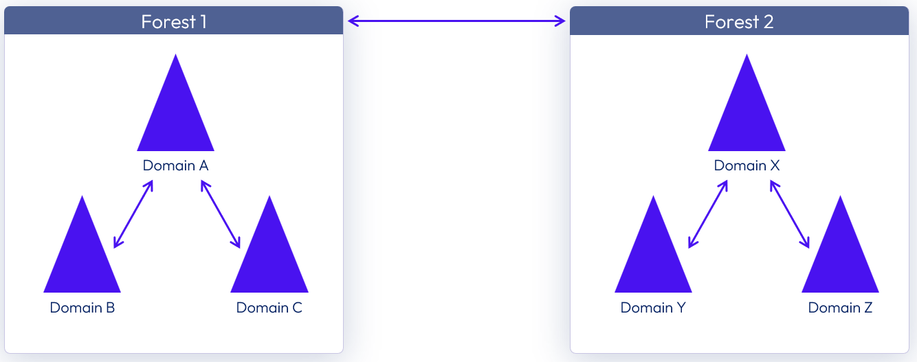
Figure 25: Two domain trees in separate forests
Users belonging to an untrusted domain can use True SSO. See Configuring Untrusted Domains.
More about domain and forest trusts can be found in Understanding the Active Directory Logical Model.
Cross-Forest scenarios
The following two scenarios show where the True SSO components and user accounts are in separate forests. In a cross-forest environment, the Enrollment Servers can be placed in any forest and in any domain. Additionally, the forest that hosts the user accounts (User Account Forest) can also have its own PKI (Public Key Infrastructure) resources.
Scenario 1: Cross-forest True SSO with PKI resources in user account forest
In this scenario, an Enterprise Certificate Authority (CA) is present in the forest that hosts the user accounts.
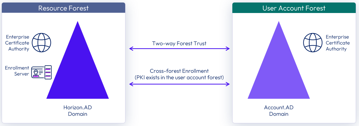
Figure 26: Cross-forest True SSO with PKI resources in the user account domain
Scenario 2: Cross-forest True SSO without PKI resources in user account forest
An Enterprise CA is not deployed in the forest which hosts the user accounts, and deploying PKI resources is not an option due to cost, resource, or other constraints.
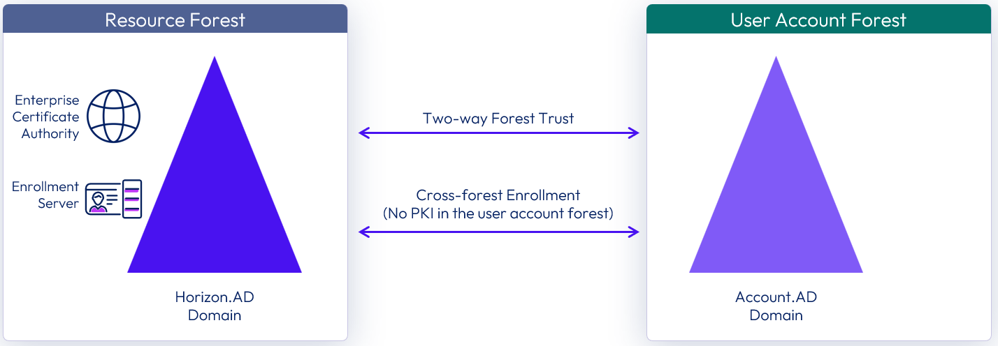
Figure 27: Cross-forest True SSO without PKI resources in the user account domain
The fundamental requirements for True SSO remain the same under each scenario. Both forests must be made aware and trust the interacting PKI objects when using True SSO across forests.
- The resource domain (Horizon.AD) must identify and validate the user account domain (Account.AD) before it can Issue client-certificate on the user's behalf.
- The user account domain (Account.AD) must identify and validate the True SSO client certificate from resource domain (Horizon.AD) to be able to authenticate the user.
Note: For more information on how to configure True SSO in a cross-forest environment, see the Implement True SSO in cross-forest environments section in Horizon 8 configuration.
Scaled single-site architecture
The following sample diagram shows the server components and the logical architecture for a single-site deployment of Horizon. For clarity, the focus of this diagram is to illustrate the core Horizon server components, so it does not include additional and optional components such as Omnissa App Volumes, Omnissa Dynamic Environment Manager, and Omnissa Access.
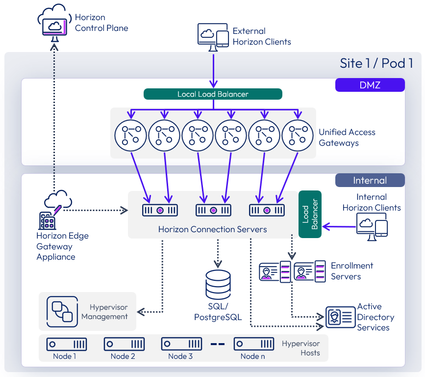
Figure 28: Single-site scaled Horizon 8 pod
Remote agents
Horizon 8 supports the deployment of Horizon Agents in a remote location from the Horizon Connection Servers. This is useful when you need to consume capacity in another data center or cloud platform without having to stand up a full Horizon pod in that location.
The recommended scale for this feature is up to 1,000 VMs in the remote location. With larger numbers, although this feature would still work, the scale becomes large enough to warrant a separate Horizon pod deployed in the cloud platform.
Networking and routing are required between the existing Horizon environment and the location where capacity is going to be consumed and the remote agents installed. One technical constraint to be aware of is that the Horizon Agents (running in the virtual desktops and RDSH hosts) must be within 120 milliseconds of latency of the Horizon Connection Servers.
See the Knowledge Base article Remote Agent Support for Horizon Enterprise for more information.
Use cases
The two common use cases for this feature are:
- Centralize Horizon 8 pods for Private Datacenters – Minimize the number of Horizon pods across multiple locations and private data centers. This is useful when virtual desktops are required to be physically in multiple locations, such as branch offices. Normally this would require separate pods per location but with the remote agent architecture, the management infrastructure can be centralized reducing the number of pods that needs to be deployed.
- Extend an existing Horizon 8 pod to consume capacity from a cloud platform – Existing Horizon pods can be extended to manage and consume capacity deployed in the cloud.
Centralizing Horizon 8 Pods for private datacenters
If Horizon desktops and RDS hosts are deployed across multiple geographic locations, instead of having to deploy and manage a separate Horizon pod next to the virtual desktop / RDSH capacity in each geographic location, this feature allows consolidation down to fewer Horizon pods that are centrally located.
For this use case, this feature applies to any currently supported version of Horizon 8.x.
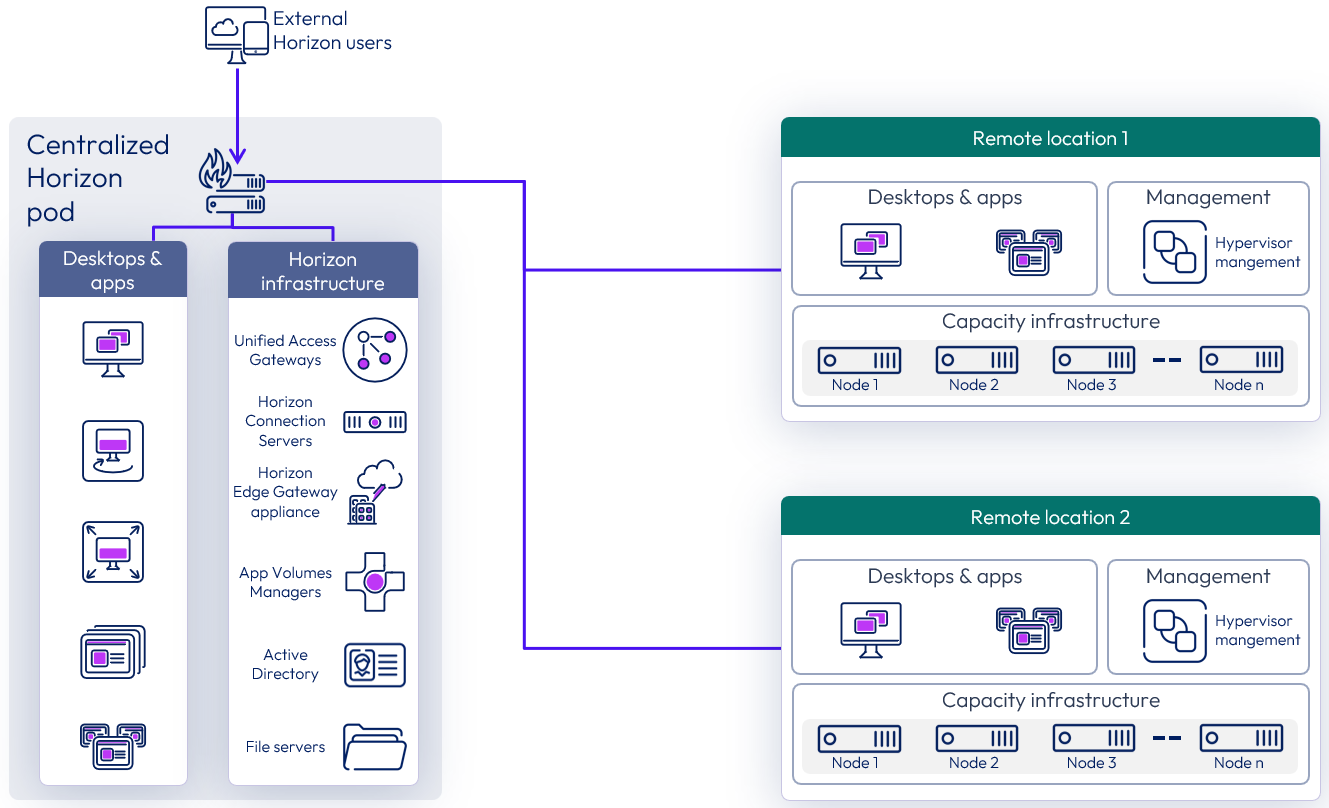
Figure 29: Centralized Horizon 8 pod consuming capacity in other private datacenters
Extending a Horizon 8 Pod to consume cloud capacity
In this scenario, existing Horizon pods, typically deployed in private data centers, can burst out to the public cloud without having to create and manage a new Horizon pod in that cloud platform. This allows the extension of existing Horizon pods to manage and use cloud capacity on one of the supported cloud platforms.
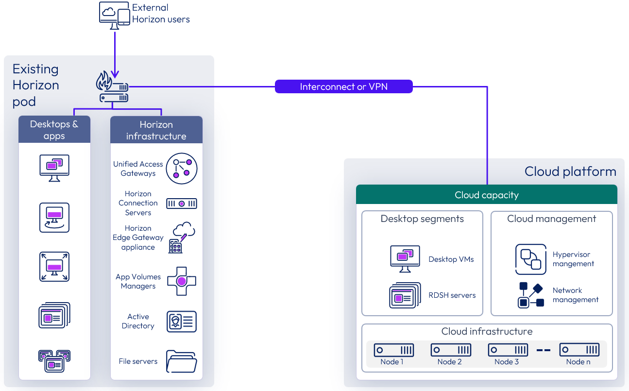
Figure 30: Extending a Horizon pod to manage cloud capacity
To add cloud capacity to an existing Horizon pod:
- Prepare the hypervisor capacity on the desired cloud platform with the number of hosts desired.
- Configure networking between the data center that hosts the existing Horizon pod and the desired cloud data center and ensure that latency is 120 milliseconds or less.
- Add the hypervisor manager of the newly created capacity to the existing Horizon pod.
- The Horizon pod can start managing the newly added cloud capacity.
Site redundancy
For the purpose of disaster recovery, we recommend at least 2 Horizon Pods located in two separate locations. If consolidating multiple locations to use a centralized Horizon Pod using this feature, consider the impact on disaster recovery and ensure that at least two locations have independent Horizon pods with their own sets of Connection Servers.
If the goal of going to the cloud is to provide a disaster recovery solution for an existing Horizon pod, it should be recognized that remote agents alone will not provide site redundancy. For disaster recovery, we recommend that you set up a separate Horizon pod in the desired cloud platform.
See Multi-site architecture and Providing Disaster Recovery for Horizon for more information on designing for multiple sites with redundancy.
Pod size
Using remote capacity (other data centers or cloud capacity) to host virtual desktops or RDSH servers and remotely deploying Horizon agents does not change the size limitations or recommendations for a single Horizon pod. See Scalability and availability.
Each Horizon pod can host a max of 20,000 sessions and can consume capacity from up to 5 hypervisor managers. Check the Omnissa Configuration Maximums for the up-to-date maximums supported.
Connection Servers
Horizon Connection Servers within a single pod must be deployed in a single location and cannot be spread across private data centers and cloud data centers. See Stretched Horizon pod - unsupported for more detail on why this is not supported.
Unified Access Gateways
Unified Access Gateways, if in use, should be deployed in the same location as the Horizon Connection Servers.
The location of the Unified Access Gateways is important as all external connections go through them and can impact latency. It is not supported to have the Unified Access Gateways for one pod spread across more than one location.
If you choose to locate the Unified Access Gateways in the same location as the remote agents, you should investigate deploying a standard Horizon pod in that location with all the management infrastructure, including the Connection Servers.
Latency
Latency between the data center where the existing Horizon pod with the Connection Servers are deployed and every single remote location where the Horizon Agents are deployed must be 120 milliseconds or less.
Networking connections between private data centers and cloud data centers vary depending on the cloud provider, we recommend that you work with your technical team as well as your cloud provider for optimal configuration.
Networking
As with any Horizon deployment, correct networking and routing must be in place to ensure the components communicate properly.
Refer to Networking and Network Ports in Horizon 8 to understand the traffic flow and port requirements.
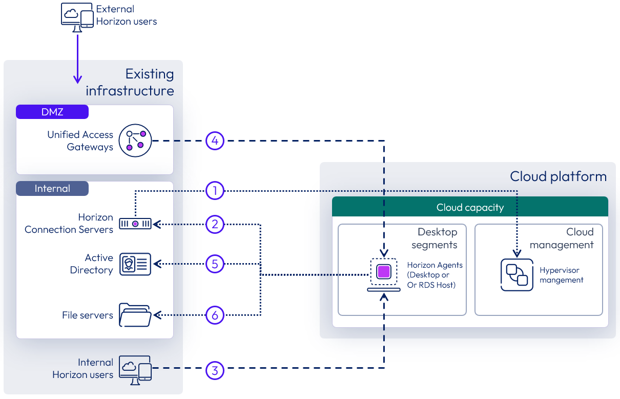
Figure 31: Remote agents networking considerations
With a remote agent deployment, attention should be paid to ensure that the components that are deployed remotely from each other can communicate properly. The diagram above highlights the key items with the numbers in circles referenced in the required traffic flows, below.
- Connection Servers to hypervisor managers.
- Horizon Agents in virtual desktops or RDS Hosts to the Connection Servers.
- For internal user sessions, the Internal Horizon Clients to Horizon Agents.
- For external user sessions, the Unified Access Gateways to Horizon Agents.
- Horizon Agents to Active Directory Domain Controllers.
- Horizon Agents to file servers.
Versions
The ability to use remote agents in a private data center applies to any currently supported version of Horizon 8.x.
When extending a Horizon pod to manage cloud capacity, the existing Horizon pod must be running Horizon 8 2006 or later. When you add the hypervisor manager that is deployed in the cloud capacity, you must select the correct deployment type. If this is selected incorrectly, clones may not be provisioned properly.
Known limitations
Horizon Control Plane services are not yet able to differentiate that capacity is deployed across multiple sites. As a result, Image Management Service functionality will not work when used on a hypervisor manager that is remote to the Connection Servers.
Multi-site architecture
This reference architecture documents and validates the deployment of all features of Horizon 8 across two data centers.
The architecture has the following primary tenets:
- Site redundancy – Eliminate any single point of failure that can cause an outage in the service.
- Data replication – Ensure that every layer of the stack is configured with built-in redundancy or high availability so that the failure of one component does not affect the overall availability of the desktop service.
To achieve site redundancy:
- Services built using Horizon 8 are available in two data centers that are capable of operating independently.
- Users are entitled to equivalent resources from both the primary and the secondary data centers.
- Some services are available from both data centers (active/active).
- Some services require failover steps to make the secondary data center the live service (active/passive).
To achieve data replication:
- Any component, application, or data required to deliver the service in the second data center is replicated to a secondary site.
- The service can be reconstructed using the replicated components.
- The type of replication depends on the type of components and data, and the service being delivered.
- The mode of the secondary copy (active or passive) depends on the data replication and service type.
Active-passive
Active-passive architecture uses two or more Horizon 8 pods of Connection Servers, with at least one pod located in each data center. Pods are joined together using Cloud Pod Architecture configured with global entitlements.
An active-passive service consumption should be viewed from the perspective of the user.
- A user is assigned to a given data center with global entitlements, and user home sites are configured.
- The user actively consumes Horizon resources from that pod and site and will only consume from the other site if their primary site becomes unavailable.
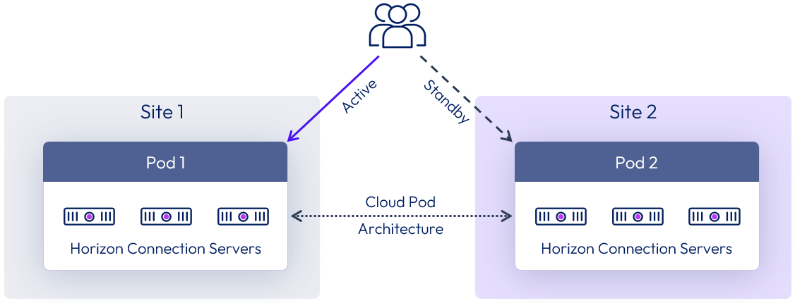
Figure 32: Active-passive architecture
Active-active
Active-active architecture also uses two or more pods of Connection Servers, with at least one pod located in each data center. The pods are joined using Cloud Pod Architecture, which is configured with global entitlements.
Again, an active-active service consumption should also be viewed from the perspective of the user.
- A user is assigned global entitlements that allow the user to consume Horizon resources from either pod and site.
- No preference is given to which pod or site they consume from.
- The challenges with this approach are usually related to replication of user data between sites.
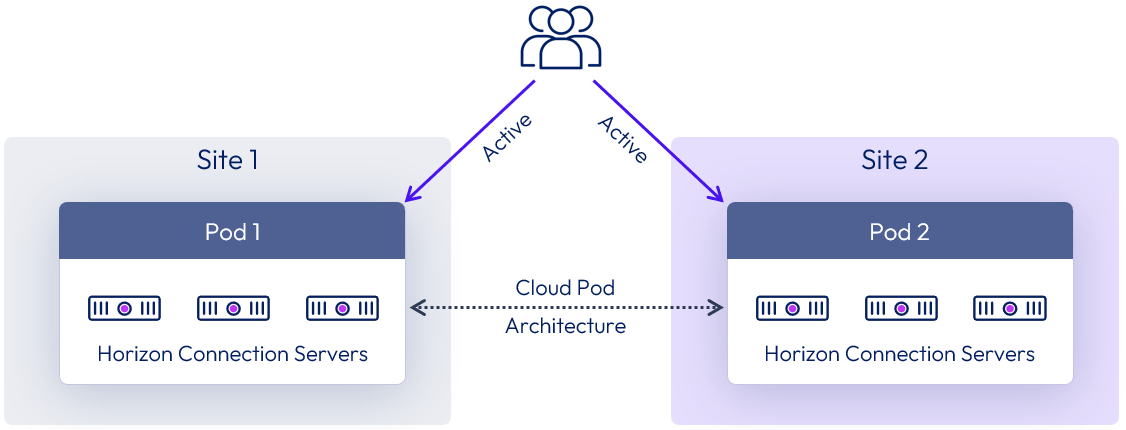
Figure 33: Active-active architecture
Stretched Horizon pod - unsupported
This architecture is unsupported and is only shown here to stress why it is not supported. Connection Servers within a given site must always run on a well-connected LAN segment and therefore cannot be running actively in multiple geographical locations at the same time.
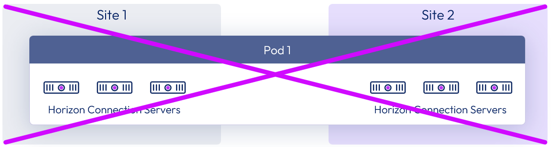
Figure 34: Unsupported stretched pod architecture
Multi-site Global Server Load Balancing
A common approach is to provide a single namespace for users to access Horizon pods deployed in separate locations. A Global Server Load Balancer (GSLB) or DNS load balancer solution can provide this functionality and can use placement logic to direct traffic to the local load balancer in an individual site. Some GSLBs can use information such as the user’s location to determine connection placement.
The use of a single namespace makes access simpler for users and allows for administrative changes or implementation of disaster recovery and failover without requiring users to change the way they access the environment.
Note the following features of a GSLB:
- GSLB is similar to a Domain Name System (DNS) service in that it resolves a name to an IP address and directs traffic.
- Compared to a DNS service, GSLB can usually apply additional criteria when resolving a name query.
- Traffic does not flow through the GSLB to the end server.
- Similar to a DNS server, the GLSB does not provide any port information in its resolution.
- GSLB should be deployed in multiple nodes in an HA or active/passive configuration to ensure that the GSLB itself does not become a point of failure.
Table 17: Strategy for Global Load Balancing
| Decision | A global server load balancer was deployed. |
| Justification | This provides a common namespace so that users can access both sites. |
Multi-site architecture diagram
The following diagram shows the server components and the logical architecture for a multi-site deployment of Horizon 8. For clarity, the focus of this diagram is to illustrate the core Horizon server components, so it does not include additional and optional components such as Omnissa App Volumes, Omnissa Dynamic Environment Manager, and Omnissa Access.
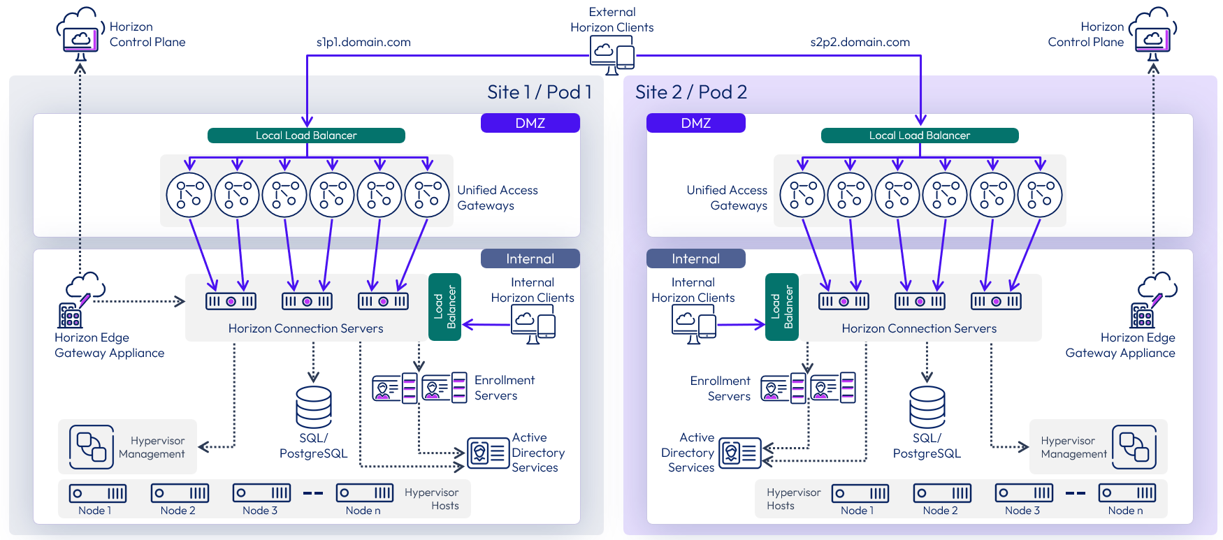
Figure 35: Multi-site Horizon architecture
The following diagram shows the server components and the logical architecture for multiple pod deployment of Horizon, including additional components. This can be applied to pods deployed in either the same or different locations.
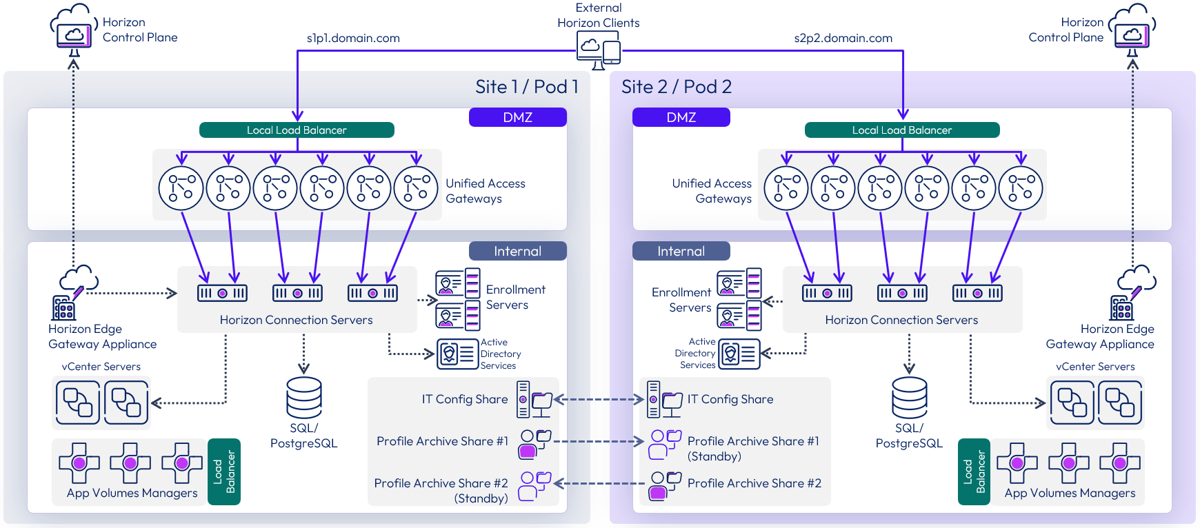
Figure 36: Multiple Horizon pods with additional services
Each site has a separate instance of App Volumes with its own set of App Volumes Managers. For more information, see Multi-site design in App Volumes architecture.
Each site has a set of file shares for Dynamic Environment Manager. The IT Config share can be replicated and made available in both sites as users only require read access. The Profile Archive shares are active to users in one site only, although they can be replicated to an alternative location, to be used in an outage event. For more information, see Multi-site design in Dynamic Environment Manager architecture.
VMware vSphere deployments
This section gives specific considerations when deploying Horizon 8 in a VMware vSphere environment.
Note: The numbers, limits, and recommendations given in this section were correct at the time of writing. For the most current numbers for Horizon 8 when deployed on VMware vSphere, see the Omnissa Configuration Maximums.
Availability on VMware vSphere
When deploying Horizon management servers on vSphere clusters, you can provide availability for individual server instances:
- vSphere High Availability (HA) can be used to restart a management VM in the event of a vSphere host failure. For more information, see How vSphere HA Works.
- DRS rules are configured to ensure that management servers, and in particular those performing the same role, do not reside on the same vSphere host.
- To provide continuous availability, vSphere Fault Tolerance can be used with management VMs. For more information, see Providing Fault Tolerance for Virtual Machines. Note that Fault Tolerance is typically not recommended for components such as Connection Servers, where providing resiliency and redundancy by adding additional server instances is the preferred approach.
Pod and block considerations on VMware vSphere
Review the general guidance given in the pod and block section. In a vSphere deployment, the resource capacity for a pod is provided by one or more resource blocks.
- Each block is made up of one or more resource vSphere clusters.
- Each block has its own vCenter Server.
The number of virtual machines (VMs) a block can typically host depends on the type of Horizon VMs used. Resource blocks can be either in the same location as the Connection Servers or in a different location, using the Remote agents deployment model.
VMware vCenter Server
vCenter Server is the delimiter of a resource block when VMware vSphere is used to host Horizon 8 VMs. The recommended number of VMs that a single vCenter Server can typically host depends on the type of Horizon VMs used. The following limits have been tested.
- 20,000 instant-clone VMs
- 4,000 full-clone VMs
When sizing vSphere resource blocks and the number of vCenter Servers you should consider avoiding a single point of failure, ensuring the required performance, and providing availability of the functions that vCenter provides. Just because configuration maximums are published does not mean you should necessarily design to those limits.
Single point of failure
Using a single vCenter Server will introduce a single point of failure that could affect too large a percentage of the VMs in your environment. The vCenter being unavailable will affect operations, such as provisioning of VMs, refreshing VMs as users logout, or powering on or off of VMs. Therefore, carefully consider the size of the failure domain and the impact should a vCenter Server become unavailable.
A single vCenter Server might be capable of supporting your whole environment, but to reduce risk and minimize the impact of an outage, you will probably want to include more than one vCenter Server in your design.
Performance
Sizing can also have performance implications because a single vCenter Server could become a bottleneck if too many provisioning tasks run at the same time. Do not just size for normal operations but also understand the impact of provisioning tasks and their frequency.
For example, consider a use case with non-persistent, parent-based, instant-clone desktops, which are deleted after a user logs off and are provisioned when replacements are required. Although a non-persistent, floating desktop pool can be pre-populated with spare desktops, it is important to understand how often replacement VMs would need to be generated and when that happens. Are user logoffs and the demand for new desktops spread throughout the day? Or are desktop deletion and replacement operations clustered at certain times of day? If these events are clustered, can the number of spare desktops satisfy the demand, or do replacements need to be provisioned? How long does provisioning desktops take, and is there a potential delay for users?
Understanding provisioning tasks, like this, helps understand the demand placed on the vCenter Server and whether it is better to scale out rather than scale up.
Availability
You can increase the availability of vCenter Server by using vSphere High Availability (HA), which restarts the vCenter Server VM in the event of a vSphere host outage. vCenter High Availability can also be used to provide an active-passive deployment of vCenter Server appliances, although caution should be used to weigh the benefits against the added complexity of management.
Implementation strategy for vCenter Server
Table 18: Implementation strategy for vCenter Server
| Decision | Two resource blocks were deployed per site, each with their own vCenter Server virtual appliance, located in the internal network. |
| Justification | A single resource block and a single vCenter Server are supported for the intended target of 8,000 instant-clone VMs; however, having a single vCenter Server for the entire user environment presents too large a failure domain. Splitting the environment across two resource blocks, and therefore over two vCenter Servers reduces the impact of any potential outage. This approach also allows each resource block to scale to a higher number of VMs and allow for growth, up to the pod recommendation, without requiring us to rearchitect the resource blocks. |
Co-hosting management and end user resources on vSphere
As covered in Co-hosting management and end user resources, there are options available regarding the location of management components, such as Connection Servers, including:
- Co-located the management servers on the same vSphere hosts as the desktops and RDSH servers that will serve end-users.
- Hosting them on a separate vSphere cluster.
If you place everything on the same vSphere cluster, you should
- Ensure resource prioritization for the Horizon 8 management components.
- Size resources (for example, virtual desktops) to take into account the overhead of the management servers.
See vSphere Resource Management for more information on how to configure resource prioritization on vSphere.
Instant clone smart provisioning
When using Sphere capacity, an automated instant clone pool or farm is created from a golden image VM using the vSphere instant clone API.
Horizon 8 creates several types of internal VMs (Internal Template, Replica VM, and Parent VM) to manage these clones in a more scalable way. Instant clones share the virtual disk of the replica VM and therefore consume less storage than full VMs. In addition, instant clones share the memory of the parent VM when they are first created, which contributes to fast provisioning. After the instant clone VM is provisioned and the machine starts to be used, additional memory is utilized. After it is provisioned, the clone is no longer linked to the parent VM.
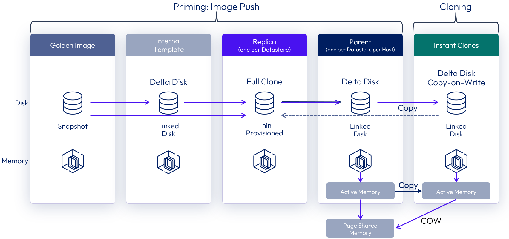
Figure 37: Instant clones with parent VMs
Although helpful in speeding up the provisioning speed, the use of a parent VM does increase the memory requirement across the cluster. When there is a low density of VM clones per host, either with small desktop pools or with RDS Host farms, the benefit of having more memory outweighs the increase in provisioning speed. In this case, Horizon can automatically choose to provision instant clones directly from the replica VM, without creating any parent VM.
This feature is called smart provisioning, and the key differences include:
- No running parent VMs are created on the vSphere hosts.
- Each clone has a vSphere snapshot taken, after cloning from the replica, which it is reverted to at logoff.
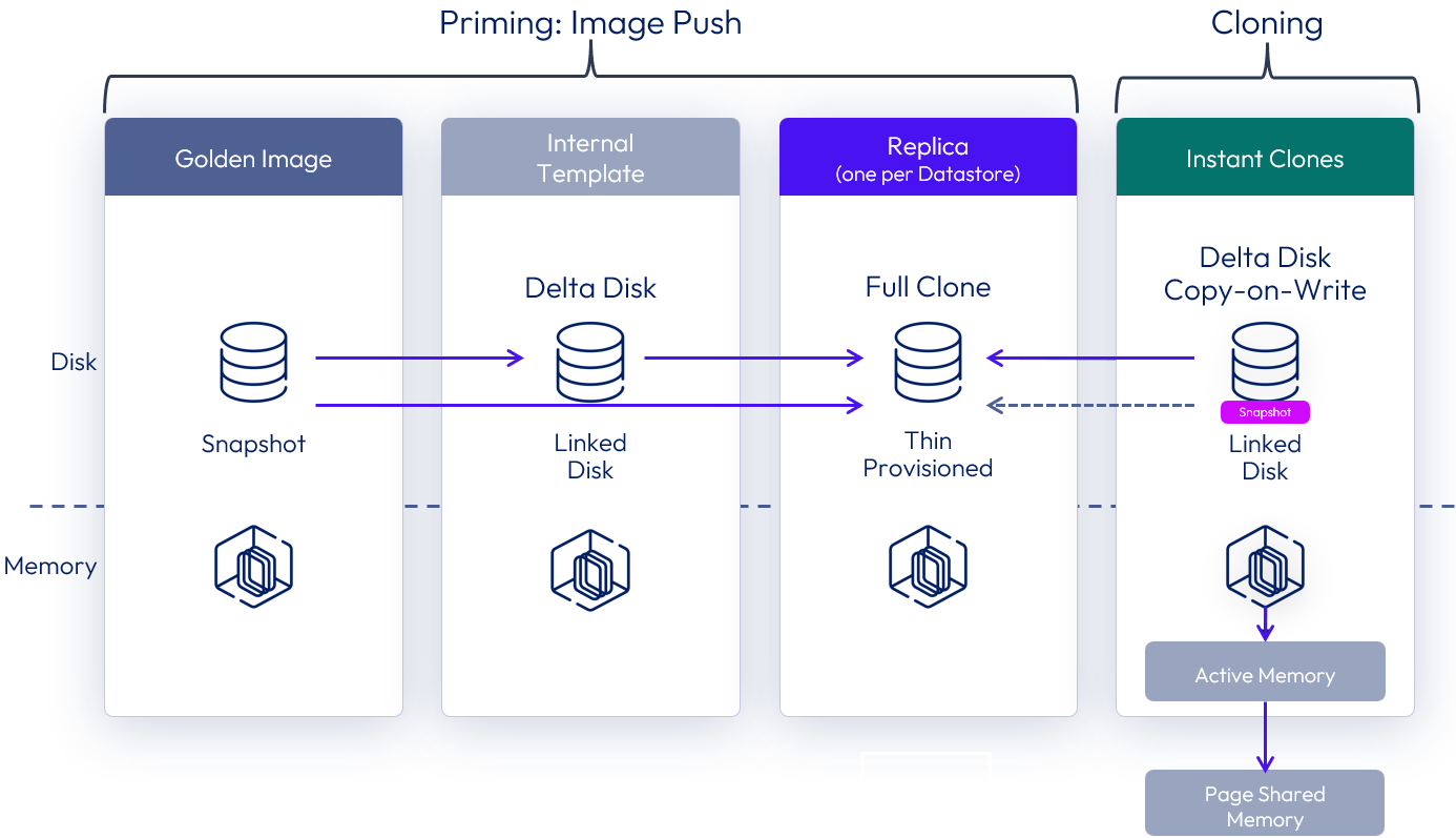
Figure 38: Instant clones without parent VMs
A single instant clone pool or farm can have both instant clones that are created with parent VMs (mode A) or without parent VMs (mode B). The default behavior can be overridden at a pool or farm level. See How to switch provisioning scheme for an Instant Clone Pool or Farm.
See the Horizon documentation Instant-Clone Desktop Pools and Creating an Automated Instant-Clone Farm.
Nutanix AHV deployments
This section gives specific considerations when deploying Horizon 8 in a Nutanix AHV environment and is intended to supplement the general guidance given in this document.
- Nutanix AHV (Acropolis Hypervisor) is a bare-metal hypervisor that is part of the Nutanix hyperconverged infrastructure (HCI) platform.
- Nutanix AOS (Acropolis Operating System) is the core software that powers Nutanix’s hyperconverged infrastructure, combining compute, storage, and virtualization into a unified platform. An AOS instance is deployed on each hypervisor node.
- Nutanix Prism Central is the management control plane and console for managing one or more Nutanix clusters. It is the key integration point between Omnissa Horizon 8 and Nutanix AHV environments.
Pod and block considerations on Nutanix AHV
The fundamental architecture of Horizon 8 remains the same when using AHV as the capacity provider. Scaling and availability should be designed using the Horizon pod and block architecture as this approach gives you a predictable, repeatable, and scalable method of designing Horizon 8 environments.
- A pod is a Horizon construct which is delimited by the Horizon Connection Servers, and the design guidance given in Scalability and availability should be followed.
- The resource capacity for a Horizon pod is provided by one or more AHV-based resource blocks.
Each AHV resource block should be designed in a scalable, repeatable manner and provide a degree of isolation from other blocks.
- A resource block is made up of one or more Nutanix AHV clusters.
- A resource block should have a dedicated Prism Central management instance. This ensures separation between blocks, thereby enhancing resiliency and reducing the impact of domain failure.
- A Prism Central instance can manage multiple AHV clusters.
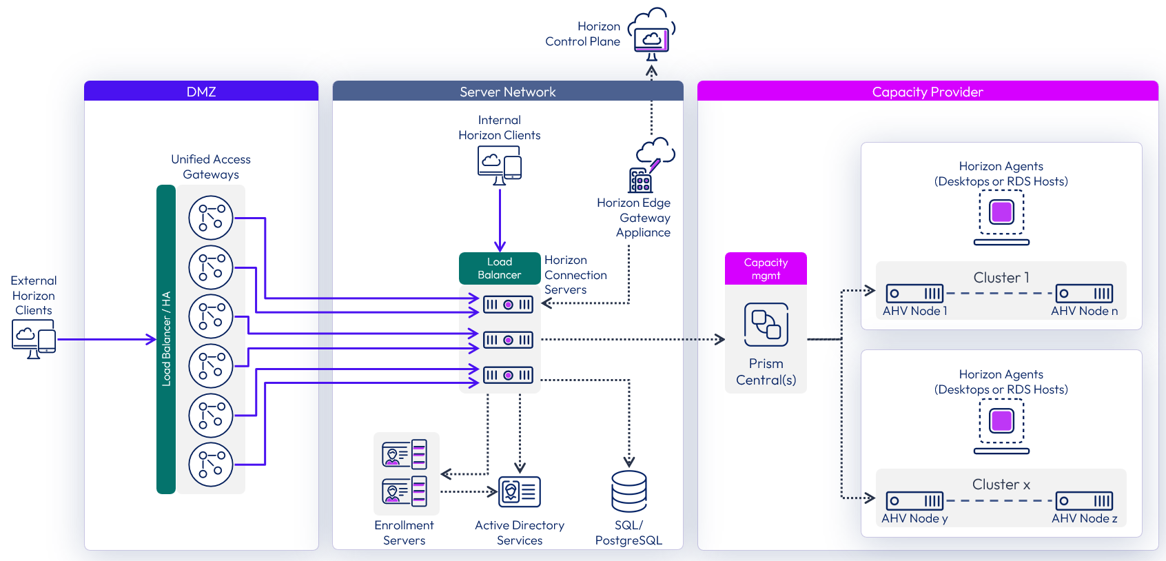
Figure 39: Scaled Horizon 8 pod with Nutanix AHV
The number of virtual machines (VMs) a resource block can typically host depends on the resources available in the Nutanix AHV clusters, and on sizing of the Prism Central instance for the block.
Resource blocks can be either in the same location as the Connection Servers or in a different location, using the Remote agents deployment model.
Nutanix AHV
Use the following guidelines and recommendations to design AHV-based resource blocks.
Nutanix AHV cluster sizing
When designing AHV clusters for use with Horizon 8, follow the recommendations for sizing AHV clusters and for VM density.
Maximums - The Nutanix Configuration Maximums for AHV shows the following maximum numbers, but you should not design to maximums.
- Cluster size - The maximum AHV hosts per cluster is 32
- VMs per host - The maximum powered on VDI VMs per AHV node is 200.
- VMs per cluster - The maximum number of powered-on VMs per AHV cluster is 4096.
Recommendations - Nutanix give the following as more realistic sizing recommendations for a VDI deployment:
- Cluster size - Use a maximum of 16 AHV nodes per cluster for VDI workloads as a more realistic sizing guideline. You should also factor in redundancy of at least n+1, giving a usable capacity equivalent of 15 AHV nodes.
- VMs per host – The number of VMs you can host per AHV node will depend on many factors, including the host resources, the demands of each VM, and how the user uses it. Nutanix gives a rough guideline of about 150 VDI VMs per node.
- VMs per cluster – Using the above sizing recommendations of up to 16 AHV nodes in a cluster, with n+1 redundancy, with each node hosting up to 150 VDI VMs, guidance for a cluster is to host up to 2,250 VMs.
You should also consider the size of the failure domain when consider VM to host density, and also when sizing clusters.
- Designing for a high number of VMs per AHV node might impact an unacceptable number of users due to a host failure.
- Using larger clusters might result in a large percentage of users being impacted if any issue occurs at the cluster level. Using more, smaller clusters may provide better resilience by separating resources.
Nutanix AHV storage sizing
You should work with Nutanix to correctly size your hardware and storage requirements.
An important aspect to consider when sizing storage is how Nutanix AHV manages its storage reclamation process. This consideration becomes particularly relevant during updates to Horizon pools and farms, when a push image operation is performed:
- The existing clone VMs are deleted along with their recovery points.
- New clone VMs are then created, and new recovery points are generated for them.
- However, the deleted VMs and their recovery points are not immediately removed from physical storage. They remain on disk until Nutanix AHV runs its storage reclamation process, which happens in hourly cycles.
Due to this behavior, initiating an image push results in a temporary rise in storage utilization. Nutanix AHV implements a redirect-on-write storage technique, which typically ensures that each new clone consumes only a small amount of additional space, minimizing the impact of this.
However, if Bitlocker is enabled on the VMs and their drives are encrypted, each VM uses the entire disk space that has been allocated to it. This will significantly increase the temporary storage spike during image push operations.
Recommendation – Ensure that drives are not encrypted, and Bitlocker cannot restart and turn back on encryption. When you build gold images for use on AHV ensure that you follow the process in Manually creating optimized Windows images for Horizon VMs, in particular the following steps:
- Turn off device encryption for Windows drives.
- Disable Bitlocker to prevent it turning back on device encryption.
Nutanix Controller Virtual Machine sizing
Each Nutanix AHV node hosts a Controller VM (CVM), running Nutanix AOS as a worker or leader instance, which manages host and cluster services, including:
- Serving all I/O operations to all the VMs running on the host.
- Managing distributed file systems, such as handling user I/O, data placement, and metadata management while ensuring data integrity and availability.
- Managing garbage collection for space reclamation and storage efficiency improvement through data compression, deduplication, and erasure coding.
- Optimizing the system's performance.
- It also plays a role in data protection mechanisms like snapshots and replication.
The CVM's performance depends heavily on the allocated computational resources. Factors such as storage capacity, snapshot frequency, and feature usage can significantly influence the required number of logical cores. Adequate computational power is essential to ensure efficient operation, especially in denser systems.
Size the Nutanix Controller Virtual Machine (CVM) memory according to the guidance and sizing tables in the CVM Memory Configuration section of the Prism Element Web Console Guide.
Nutanix Prism Central
Prism Central manages and coordinates hypervisor resources in a Horizon deployment. Its roles include creating, cloning, and deleting virtual machines (VMs), as well as performing their power operations—all of which add to the workload of the Prism Central instance.
- Configuration maximum – While a single Prism Central instance can support up to a maximum of 25,000 VMs, depending on the resources allocated to it, you should not design to that maximum for a VDI deployment.
- Recommendation - For VDI workloads, it is recommended that each Prism Central management instance support up to a maximum of 5,000 VMs.
For more information on supported scalability and resource requirements of each size of Prism Central deployment, see the Prism Central Scalability topic in the Nutanix release notes for Prism Central version to be installed.
VM sizing for Prism Central instances
When deploying Prism Central you can select from a set of preconfigured Prism Central VM sizes. The difference is the amount of CPU and memory available to the Prism Central VM for VM management.
- Environment size - The recommended sizing for a Prism Central deployment is directly tied to the number of clusters, hosts, and VMs you intend to manage.
- Scalability - Choose a size that accommodates your current needs and allows for future growth. You can scale out a Prism Central instance later if needed.
- Features - Your choice of size may also depend on whether you need to enable and utilize advanced features, such as Microservices Infrastructure, which has its own prerequisites
Recommendation – For most Horizon deployments, use the large-sized Prism Central (single VM) deployment for each resource block. As with any infrastructure sizing, you should monitor the resource usage to understand potential bottlenecks, and in some cases, you might consider deploying X-large sized Prism Centrals.
For further information on Prism Central design, maximums, and deployment, see the following resources:
- Prism Central Architecture
- Requirements for Prism Central Deployment
- Nutanix Configuration Maximums for Prism Central
Performance of Prism Central
Sizing can also have performance implications because a single Prism Central instance could become a bottleneck if too many provisioning tasks were run at the same time. Do not just size for normal operations but also understand the impact of provisioning tasks and their frequency.
For example, consider a use case with non-persistent desktops, which are deleted after a user logs off and are provisioned when replacements are required. Although a non-persistent, floating desktop pool can be pre-populated with spare desktops, it is important to understand how often replacement VMs would need to be generated and when that happens.
- Are user logoffs and the demand for new desktops spread throughout the day?
- Or are desktop deletion and replacement operations clustered at certain times of day?
- If these events are clustered, can the number of spare desktops satisfy the demand, or do replacements need to be provisioned?
- How long does provisioning desktops take, and is there a potential delay for users?
Understanding provisioning tasks, like this, helps understand the demand placed on the Prism Central instance and whether it is better to scale out rather than scale up.
Prism Central availability
When determining the most suitable approach for ensuring the availability of Prism Central, consider the following factors:
- What functions are affected?
- A Prism Central outage impacts desktop and RDSH VM operations, such as provisioning, and power operations.
- How long would an outage last?
- Understand how long an outage would last before your chosen availability method recovers the service.
- What provisioning tasks and power operations would normally happen during that time?
- What portion of users would be potentially impacted by a Prism Central instance outage?
- If you have multiple Prism Central instances, what portion of users is affected during the outage of one of them?
- Note that an outage of Prism Central will not affect current user connections, or new connections to desktops and farms that are already provisioned and ready to use.
The methods of providing availability for Prism Central instance are:
- AHV VM high availability - The availability of each individual Prism Central VM can be increased by using AHV VM High Availability (HA), which restarts the Prism Central VM in the event of an AHV host outage.
- Three-VM (scale-out) - A Prism Central instance can be scaled out using three VMs, which enhances both capacity and, more importantly, ensures resiliency through high availability. Using three-VM scale-out Prism Central instances can add complexity and consumes additional resources.
Failure domain considerations for Prism Central instances
When sizing AHV-based resource blocks and the number of Prism Central instances you should consider avoiding a single point of failure, ensuring the required performance, and providing availability of the functions that Prism Central provides. Just because configuration maximums are published does not mean you should necessarily design to those limits.
Using a single Prism Central instance can introduce a single point of failure that could affect too large a percentage of the VMs in your environment. The Prism Central instance being unavailable will affect operations, such as provisioning of VMs, refreshing VMs as users logout, or powering on or off of VMs. Therefore, carefully consider the size of the failure domain and the impact should a Prism Central instance become unavailable.
A single Prism Central instance might be capable of supporting your whole environment, but to reduce risk and minimize the impact of an outage, you might consider including more than one Prism Central instance in your design.
Management server availability on Nutanix AHV
When deploying Horizon management servers on AHV clusters, you can provide availability for individual server instances:
- AHV VM High Availability (HA) can be used to restart a management VM in the event of an AHV host failure. For more information, see VM High Availability (HA).
- Affinity rules should be configured to ensure that management servers, and in particular those performing the same role, do not reside on the same AHV host. For more information, see Dynamic Scheduler.
Co-hosting management and end user resources on AHV clusters
As covered in Co-hosting management and end user resources, there are options available regarding the location of management components, such as Connection Servers, including:
- Co-locating the management servers on the same AHV hosts as the desktops and RDSH servers that will serve end-users.
- Hosting the management servers on a separate AHV cluster.
If you place everything on the same AHV cluster, you should:
- Ensure resource prioritization for the Horizon 8 management components.
- Size resources to take into account the overhead of the management servers.
See Dynamic Scheduler for more information.
Further resources for Horizon 8 on Nutanix AHV
For further information and guidance on deploying Omnissa Horizon 8 on Nutanix AHV, see the following resources from Nutanix:
- Omnissa Horizon on Nutanix AHV solution (Nutanix)
- Omnissa Horizon 8 on Nutanix AHV reference architecture (Nutanix)
- Disaster Recovery for Omnissa Horizon on Nutanix AHV (Nutanix)
- Best Practices for Securing Omnissa Horizon Deployments with Nutanix Flow Network Security (Nutanix)
- Omnissa App Volumes on Nutanix Best Practices (Nutanix)
Note: The numbers, limits, and recommendations given here were correct at the time of writing. For the most current numbers for Horizon 8 when deployed on Nutanix AHV, see the Omnissa and Nutanix configurations maximums guides:
- For Horizon 8 information, see the Omnissa Configuration Maximums.
- For Nutanix AHV information, see the Nutanix Configuration Maximums.
Summary and additional resources
Now that you have come to the end of this design chapter on Omnissa Horizon 8, you can return to the reference architecture landing page and use the tabs, search, or scroll to select further chapter in one of the following sections:
- Overview chapters provide understanding of business drivers, use cases, and service definitions.
- Architecture chapters give design guidance on the Omnissa products you are interested in including in your deployment, including Workspace ONE UEM, Access, Intelligence, Workspace ONE Assist, Horizon Cloud, Horizon 8, App Volumes, Dynamic Environment Manager, and Unified Access Gateway.
- Integration chapters cover the integration of products, components, and services you need to create the environment capable of delivering the services that you want to deliver to your users.
- Configuration chapters provide reference for specific tasks as you deploy your environment, such as installation, deployment, and configuration processes for Omnissa Workspace ONE, Horizon Cloud, Horizon 8, App Volumes, Dynamic Environment Management, and more.
Additional resources
For more information about Horizon 8, you can explore the following resources:
Changelog
The following updates were made to this guide:
| Date | Description of changes |
| 2026-06-24 | Updated language on connecting Horizon 8 pods to the Horizon Control Plane (replace references to connecting the Horizon Cloud Service). |
| 2026-01-14 | Added links to new and updated Nutanix guides to the Further resources for Horizon 8 on Nutanix AHV section. |
| 2025-12-18 | Guidance has been provided regarding the additional option introduced in the 2512 release, which allows the use of the extra-large Unified Access Gateway appliance to support up to 4,000 Horizon sessions per appliance. Rename references of Horizon Cloud Service – next-gen to Horizon Cloud Update URL links to 2512 documentation. |
| 2025-12-16 | New section on design guidance for Nutanix AHV deployments added. |
| 2025-05-15 | Restructured and rewritten. Diagrams updated. Separated out information and guidance on VMware vSphere deployments into its own section. Removed sections on Horizon Cloud Service – first-gen, Horizon Cloud Connector and Universal Broker -First-gen. URL links updated for 2503 releases. |
| 2025-01-14 | Graphics updated for Omnissa branding. |
| 2024-10-07 | Updated graphics and diagrams. |
| 2024-07-15 | New section on Micro-segmentation. |
| 2024-05-15 | Updated links for Omnissa docs, KB, and Tech Zone. |
| 2024-03-05 | Added cross-forest scenario guidance for True SSO. Updated links for Horizon 8 2312 |
| 2023-08-06 | Added entry and information on Events Database to the Components table. |
| 2023-07-13 | Added this Summary and Additional Resources section to list changelog, authors, and contributors within each design chapter. Updated for Horizon 8 2306. |
| 2023-06-02 | New section on Horizon Cloud Service to give guidance on connecting to the Horizon Cloud Service using the Horizon Edge Gateway appliance. Added detail to External access and the options for load balancing Connection Servers when deployed in combination with Unified Access Gateways. Various other rewrites and additions for clarity. Updated for Horizon 8 2303 |
| 2022-09-08 | Changes to reflect sizing of a Connection Server for a maximum of 4,000 connections, removing the previous recommendation of 2,000. All Horizon chapters updated with minor rewording for clarity and to cover Horizon 8 2206. |
| 2022-03-30 | Updated Pod and block guidance to clarify and align with the maximum of 20,000 VMs per pod. |
| 2021-12-14 | New section covering the new deployment option for Remote agents. Updated for Horizon 8 version 2111 |
| 2020-11-18 | Rewritten for Horizon 8. |
Author and contributors
This chapter was written by:
- Graeme Gordon, Senior Staff Architect, Omnissa.
Contributors:
- Rick Terlep, Director, Product Specialists, Omnissa.
- Leon Ngo, Senior Consultant, Professional Services, Omnissa.
Feedback
Your feedback is valuable. To comment on this paper, either use the feedback button or contact us at tech_content_feedback@omnissa.com.
.