Horizon 8 on Google Cloud VMware Engine architecture
This chapter is one of a series that make up the Omnissa Workspace ONE and Horizon Reference Architecture, a framework that provides guidance on the architecture, design considerations, and deployment of Omnissa Workspace ONE and Omnissa Horizon solutions. This chapter provides information about architecting Omnissa Horizon 8 on Google Cloud VMware Engine (referred to as GCVE throughout this document).
A companion chapter, Horizon 8 on Google Cloud VMware Engine Configuration, provides information about common configuration and deployment tasks for Horizon 8 on GCVE.
Introduction
Omnissa Horizon 8 for Google Cloud VMware Engine (GCVE) delivers a seamlessly integrated hybrid cloud for virtual desktops and applications.
It combines the enterprise capabilities of the VMware Software-Defined Data Center (SDDC), delivered as a service on Google Cloud Platform (GCP), with the market-leading capabilities of Omnissa Horizon 8 for a simple, secure, and scalable solution. You can easily address use cases such as on-demand capacity, disaster recovery, and cloud co-location without buying additional data center resources.
GCVE allows you to create VMware vSphere Software-Defined Data Centers (SDDC)s on Google Cloud Platform (GCP). These SDDCs include vCenter Server for VM management, vSAN for storage, and NSX for networking. For reference, the SDDC construct is the same as the Google term Private Cloud. We use the term SDDC in this document.
For customers who are already familiar with Horizon 8 or have Horizon 8 deployed on-premises, deploying Horizon 8 on GCVE lets you leverage a unified architecture and familiar tools. This means that you use the same expertise you know from Horizon 8 and vSphere for operational consistency and leverage the same rich feature set and flexibility you expect. By outsourcing the management of the vSphere platform, you can simplify management of Horizon 8 deployments. For more information about Horizon 8 for GCVE, visit Google Cloud VMware Engine.
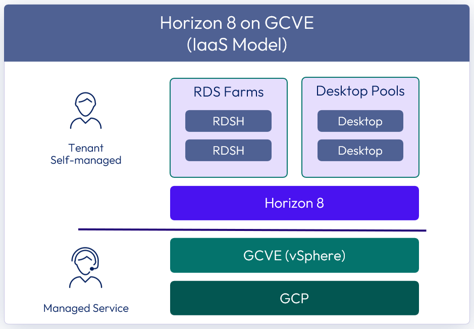
Figure 1: Horizon 8 on GCVE
For details on feature parity between Horizon 8 on-premises and Horizon 8 on GCVE, see the Knowledge Base article Horizon on Google Cloud VMware Engine (GCVE) Support (81922).
The purpose of this design chapter is to provide a set of best practices on how to design and deploy Horizon 8 on GCVE. This guide is designed to be used in conjunction with:
| Important | It is highly recommended that you review the design concepts covered in the Horizon 8 Architecture chapter. This chapter builds on the Horizon 8 Architecture chapter and only covers specific information for Horizon 8 on GCVE. |
Table 1: Horizon 8 on GCVE strategy
| Decision | A Horizon 8 deployment was designed and deployed on GCVE. The environment was designed to be capable of scaling to 4,000 concurrent connections per SDDC for users. This per SDDC number is valid regardless of Architecture chosen. |
| Justification | This strategy allowed the design, deployment, and integration to be validated and documented. |
Deployment options
There are two possible deployment options for Horizon 8 on GCVE:
- All-in-SDDC architecture - A consolidated design with all the Horizon components located inside each SDDC. This design will scale to approximately 4,000 concurrent users per SDDC. Each SDDC is deployed as a separate Horizon pod.
- Federated architecture – A design where the Horizon management components are located in the Google Compute Engine and the Horizon resources (desktops and RDS Hosts for published applications) are located in the GCVE SDDCs. This design is still limited to approximately 4,000 concurrent users per SDDC but supports Horizon pods that consume multiple SDDCs. Since this design places the Unified Access Gateway appliances in Google Cloud Platform (GCP) and in front of the NSX edge appliances in the SDDC, standard Horizon limits will apply to the size of the Architecture. It is scaled and architected the same way as on-premises Horizon. See Omnissa Configuration Maximums for details.
Note: 4,000 concurrent users per SDDC is given as general guidance. The volume of network traffic to and from the virtual desktops or published applications, and the throughput into and out of the SDDC, has an impact on the number of sessions per SDDC possible. Testing should be carried out to determine the number of sessions that can be supported based on the actual workload and network traffic.
All-in-SDDC architecture
In the SDDC-based deployment model, all components, including management, are located inside the GCVE SDDC (Private Cloud). Each SDDC would host a separate Horizon pod and with the All-in-SDDC architecture, a Horizon pod should not contain multiple SDDCs.
The following figure shows the high-level logical architecture of this deployment model and all the management components inside the SDDC. There is a customer-provided load balancer that sits in the Google Compute Engine to forward Horizon protocol traffic into the SDDC.
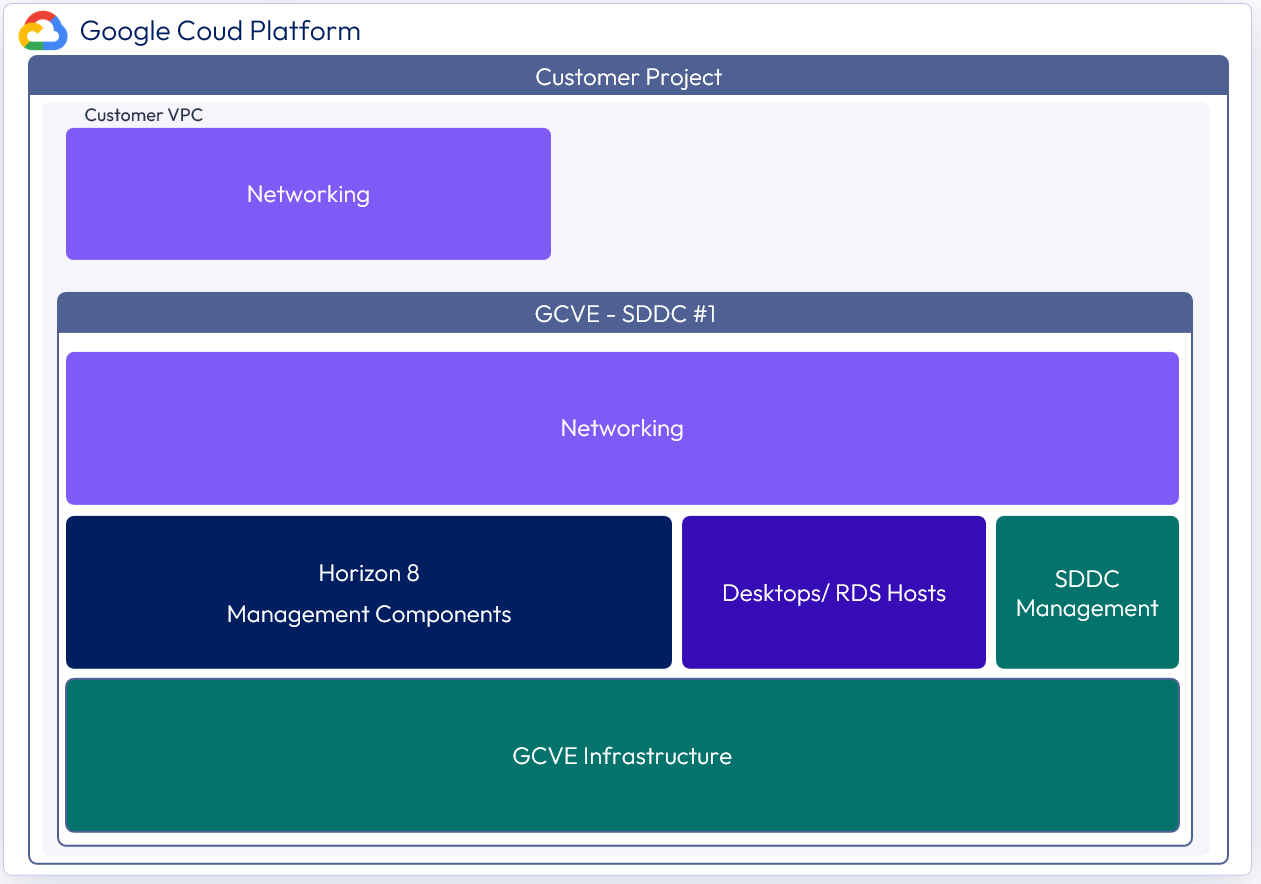
Figure 2: Logical view of the All-In-SDDC architecture of Horizon 8 on GCVE
In this design, because all management components are located inside the SDDC, this can potentially lead to display protocol hairpinning. If using global entitlements as part of cloud pod architecture or using a single namespace, the user could be directed to either pod. If the users’ resource is not in the SDDC that they are initially directed to for authentication, their Horizon protocol traffic would go into the initial SDDC to the Unified Access Gateway, then back out via the NSX edge, and then be directed to where their desktop or published application is being delivered from. This causes a reduction in achievable scale due to this protocol traffic hairpinning.
For this reason, Horizon Cloud Pod Architecture is not recommended with the All-in-SDDC Architecture on GCVE.
In this design, each SDDC represents a separate Horizon pod and would have a unique name (for example, desktops1.company.com). Universal Broker, or Workspace ONE Access can be used to present users with a single initial FQDN for authentication and resource choice. Alternatively, users would connect directly to each pod’s FQDN with the Horizon Client.
Federated architecture
In the federated deployment model, all Horizon management components are located in the Google Compute Engine. The desktop / RDS capacity is located inside each SDDC. With the Federated Architecture a single Horizon pod can be scaled to include multiple SDDC and address large scale deployments needs. The following figure shows the high-level logical architecture of this deployment model with all the management components in Google Compute Engine. In this design, the built-in Google load balancer can be used to load balance the UAG appliances, and no customer-provided load balancer is required.
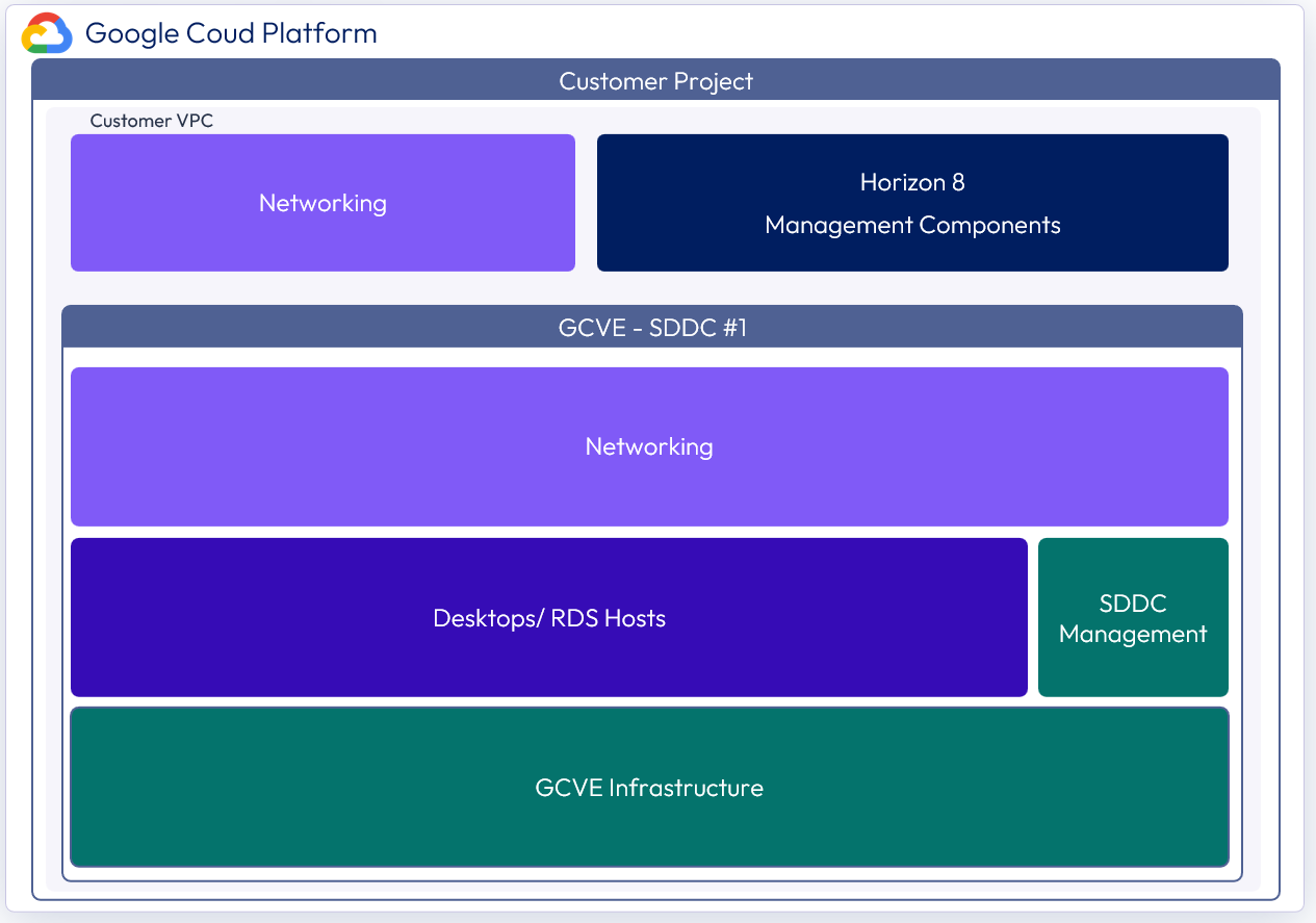
Figure 3: Logical view of the federated architecture of Horizon 8 on GCVE
Architectural overview
The components and features that are specific to Horizon 8 on GCVE are described in this section.
Components
The individual server components used for Horizon 8, whether deployed on GCVE or on-premises, are the same. They are also the same whether deployed in the Federated or All-in-SDDC Architecture. The main difference is where the components are placed. See the Components section in Horizon 8 Architecture for details on the common server components.
Check the knowledge base article 81922 for feature parity of Horizon 8 on GCVE. The components and features that are specific to Horizon on GCVE are described in this section.
Software-Defined Data Centers (SDDC)
GCVE allows you to create vSphere Software-Defined Data Centers (SDDCs) on Google Cloud Platform (GCP). These SDDCs include vCenter Server for VM management, vSAN for storage, and NSX for networking. For reference, the SDDC construct is the same as the Google term Private Cloud.
You can connect an on-premises SDDC to a cloud SDDC and manage both from a single vSphere Web Client interface. Review the GCVE Prerequisites document for more details on requirements. You log in to https://console.cloud.google.com/ to access both your GCP and GCVE environments. For more information, see the GCVE documentation.
Important: If you are deploying more than one SDDC in GCVE for use with Horizon 8, make sure to use unique CIDR (a method for allocating and routing IP addresses) for the management components. By default, they use the same CIDR and have the same IP addresses. If you do not change this default, you will not be able to use the multiple vCenters with Horizon. For more information, see the GCVE documentation on setting up a private cloud.
After you have deployed an SDDC on GCVE, you can deploy Horizon in that cloud environment just like you would in an on-premises vSphere environment. This enables Horizon customers to outsource the management of the SDDC infrastructure. There is no requirement to purchase new hardware, and you can choose between two pricing options for GCVE nodes:
- On-demand pricing - Prices are based on your hourly usage in a particular region.
- Commitment-based pricing - Prices are discounted in exchange for committing to continuously use GCVE nodes in a particular region for a one- or three-year term.
SDDC management components
The management components for the SDDC include vCenter Server and NSX. These components are managed by Google. Google will handle upgrades and maintenance of these components at the infrastructure level. The management interfaces are available to customers to manage vSphere and NSX.
See the Get sign-in credentials section in the GCVE documentation for details.
Compute components
The compute component includes the following Horizon infrastructure components:
- Horizon Connection Servers
- Unified Access Gateway appliances
- App Volumes Managers
- Virtual Desktops
- RDSH Hosts
- Database Servers
- App Volumes
- Horizon Events database
- Horizon Edge Gateway appliance (used when connecting to Horizon Cloud Service – next-gen)
NSX components
NSX is the network virtualization platform for the Software-Defined Data Center (SDDC), delivering networking and security entirely in software, abstracted from the underlying physical infrastructure.
Important: The maximum number of ports per logical network is 1000, but you can create multiple pools using different logical networks.
- Tier-0 router – Handles Internet, route or policy based IPSEC VPN, and serves as an edge firewall for the Tier-1 Compute Gateway (CGW).
- Tier-1 Compute Gateway (CGW) – Serves as a distributed firewall for all customer internal networks.
- The Tier-1 Management Gateway (MGW) – Serves as a firewall for the Google-maintained components like vCenter and NSX.
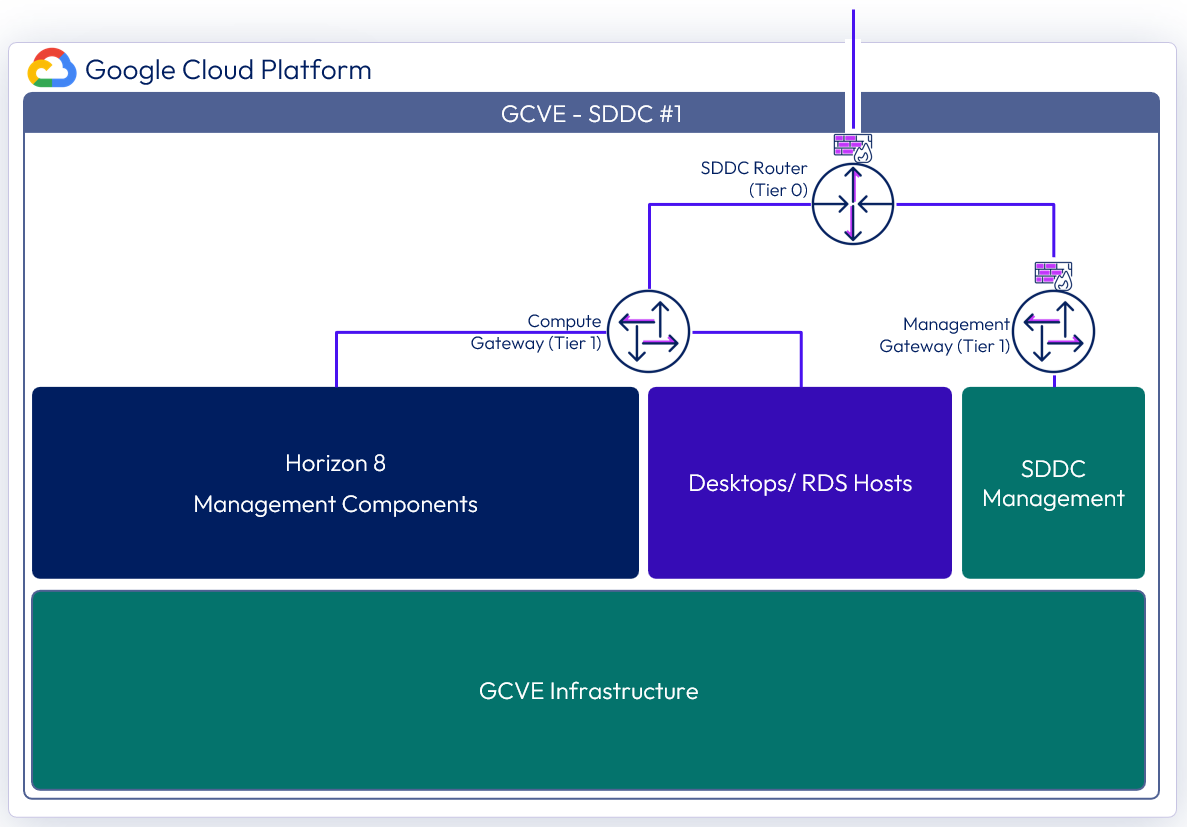
Figure 4: NSX components in the All-in-SDDC architecture per SDDC
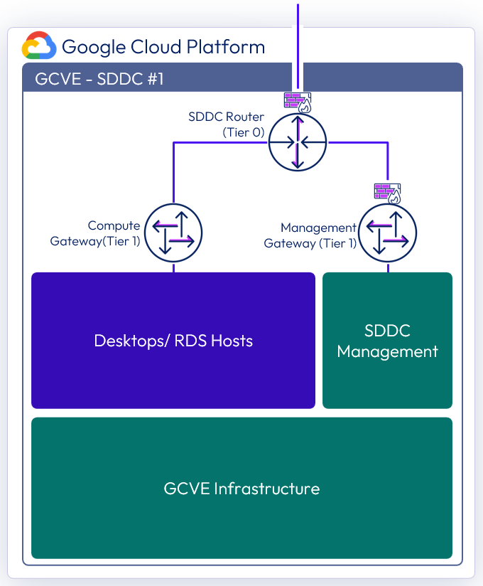
Figure 5: NSX components in the federated architecture per SDDC
Resource pools
A resource pool is a logical abstraction for flexible management of resources. Resource pools can be grouped into hierarchies and used to hierarchically partition available CPU and memory resources.
Within a Horizon pod on GCVE, you can use vSphere resource pools to separate management components from virtual desktops or published applications workloads to make sure resources are allocated correctly.
After a GCVE SDDC is provisioned, two resource pools exist:
- A Workload Resource Pool - Described below
- HCX Management - Not in the scope of this Reference Architecture
All-In-SDDC architecture strategy for resource pools
In the All-in-SDDC architecture, both management and user resources are deployed in the same SDDC. It is recommended to create two sub-resource pools within the Workload Resource Pool for your Horizon deployments:
- A Horizon Management Resource Pool for your Horizon management components, such as connection servers
- A Horizon User Resource Pool for your desktop pools and published applications.

Figure 6: Resource pools for All-in-SDDC architecture of Horizon 8 on GCVE
Federated architecture strategy for resource pools
In the federated architecture, only the desktop and RDS resources are located inside of the GCVE SDDC. There is no need to create sub-resource pools. The Workload resource pool can be used.

Figure 7: Resource pools for the federated architecture of Horizon 8 on GCVE
Scalability and availability
This section covers the concepts of pods and blocks, Cloud Pod architecture, Horizon Universal Broker, Workspace ONE Access, and Sizing Horizon 8 on GCVE.
Pod and block
A key concept of Horizon, whether deployed on GCVE or on-premises, is the use of blocks and pods. See the Pod and Block section in Horizon 8 Architecture.
Cloud Pod Architecture
Cloud Pod Architecture (CPA) is a standard Horizon feature that allows you to connect your Horizon deployment across multiple pods and sites for federated management. It can be used to scale up your deployment, to build hybrid cloud, and to provide redundancy for business continuity and disaster recovery. CPA introduces the concept of a global entitlement (GE) that spans the federation of multiple Horizon pods and sites. Any users or user groups belonging to the global entitlement are entitled to access virtual desktops and RDS published apps on multiple Horizon pods that are part of the CPA.
Important: CPA is not a stretched deployment; each Horizon pod is distinct and all Connection Servers belonging to each of the individual pods are required to be located in a single location and run on the same broadcast domain from a network perspective.
Here is a logical overview of a basic two site/ two pod CPA implementation. For GCVE, Site 1 and Site 2 might be different GCP regions, or Site 1 might be on-prem and Site 2 might be on GCVE.

Figure 9: Cloud Pod Architecture
For the full documentation on how to set up and configure CPA, refer to Cloud Pod Architecture in Horizon 8 and the Cloud Pod Architecture section in Horizon 8 Configuration.
In the All-in-SDDC Architecture, because all management components are located inside the SDDC, this can lead to protocol hairpinning. Users could be directed to either pod with a global entitlement. If the users’ resource is not in the SDDC they get directed to, they are directed back out via the NSX edge and directed to the other site. This causes reduction in scale due to this protocol hairpinning. For this reason, we are not supporting the use of Horizon Cloud Pod Architecture with the All-in-SDDC Architecture.
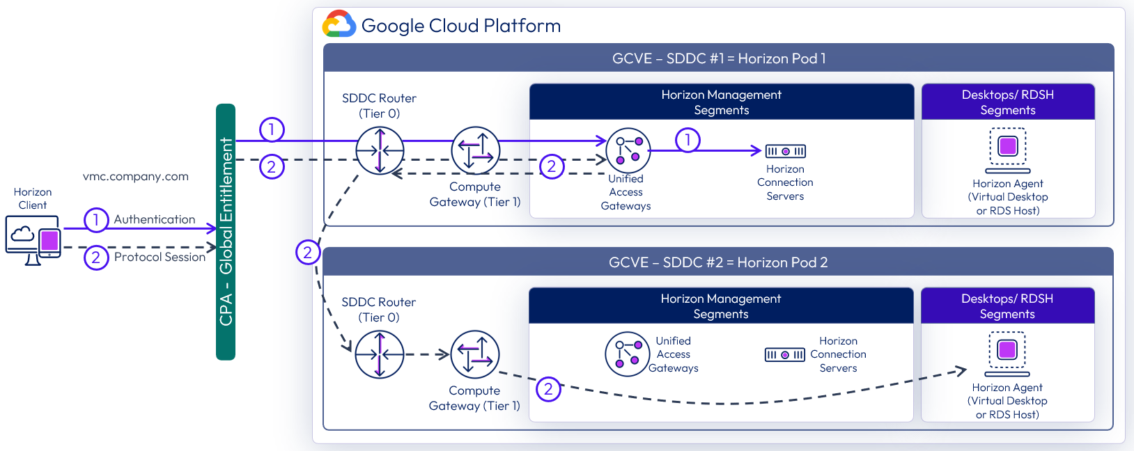
Figure 10: Horizon protocol traffic hair pinning with All-in-SDDC design (UAGs inside of SDDC)
Using CPA to build hybrid cloud and scale for Horizon
You can deploy Horizon in a hybrid cloud environment when you use CPA to interconnect Horizon on-premises and Horizon pods on Horizon on GCVE with the Federated Architecture. You can easily entitle your users to virtual desktop and RDS published apps on-premises and/or on Horizon on GCVE. You can configure it such that they can connect to whichever site is closest to them geographically as they roam.
You can also stretch CPA across Horizon pods in two or more GCVE SDDCs with the same flexibility to entitle your users to one or multiple pods as desired. Of course, use of CPA is optional, and not recommended with the All-in-SDDC architecture. There is still risk of Horizon protocol hairpinning if using Horizon pods in locations behind different UAG appliances. An example would be a Federation created with one Horizon pod on-premises and one Horizon pod in GCVE. With a Global Entitlement, the user may be directed to the GCVE environment, if the user’s resource is not located in that Horizon pod, it will go back out of the Horizon pod and direct the user to the other pod located on-premises.
Omnissa Access
Omnissa Access (formerly Workspace ONE Access) can be used to broker Horizon resources. In this case, the entitlements and resources are synced to Access, and Access knows the FQDN of each Horizon pod to properly direct users to their desktop or application resources. When a user logs into Workspace ONE Access, they are presented with icons for each desktop and application they are entitled to. They do not need to worry about FQDNs, they just click the resource, and they are connected. In the federated architecture, Cloud Pod Federations can also be added to Workspace ONE Access.
For more design details, see Horizon and Workspace ONE Access Integration in the Platform Integration chapter.
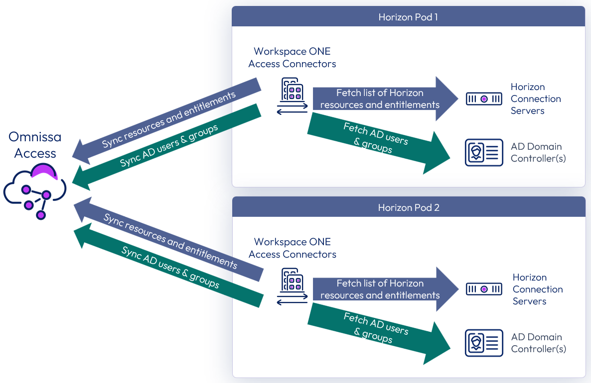
Figure 11: Syncing Horizon resources into Omnissa Access
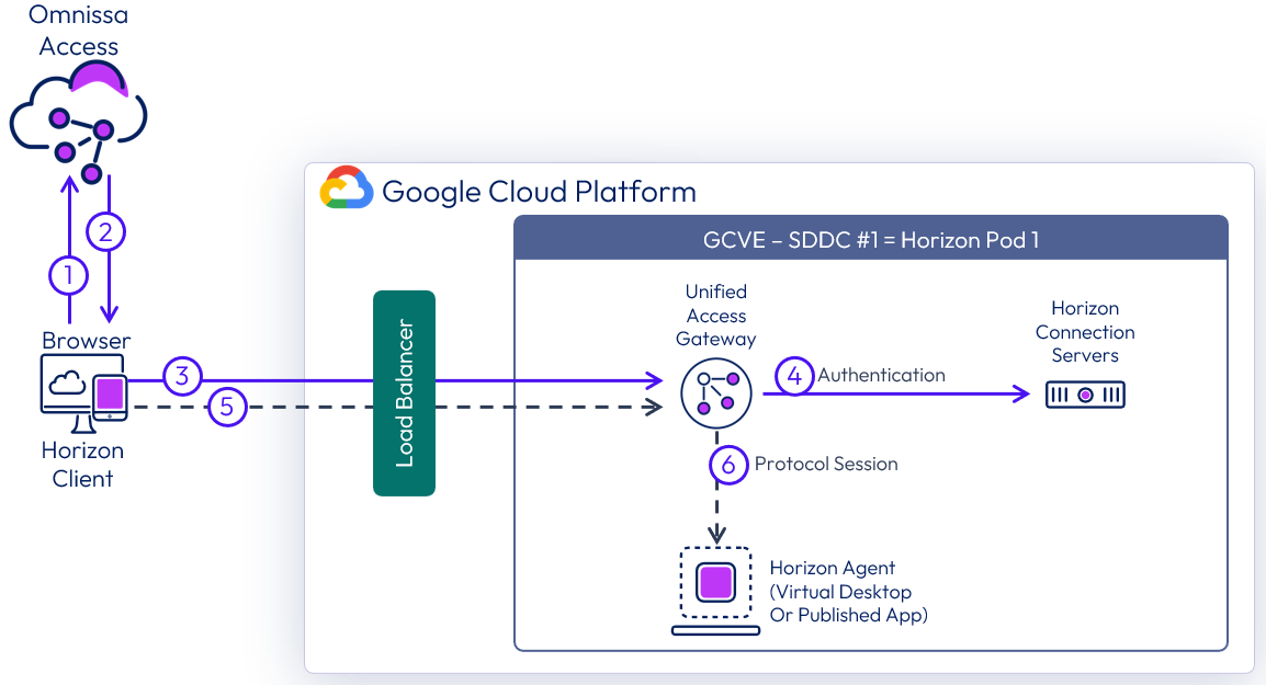
Figure 12: Brokering into Horizon resources using Access with All-in-SDDC architecture
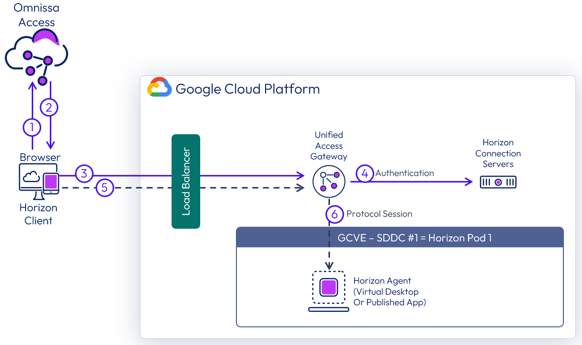
Figure 13: Brokering into Horizon resources using Access with the federated architecture
Sizing Horizon 8 on GCVE
Similar to deploying Horizon on-premises, you must size your requirements for deploying Horizon 8 on GCVE to determine the number of hosts you will need to deploy. Hosts are needed for the following purposes:
- Your virtual desktop or RDS workloads.
- Your Horizon infrastructure components, such as connection servers, Unified Access Gateways, App Volumes managers.
- SDDC infrastructure components on GCVE. These components are deployed and managed automatically for you by Google.
The methodology for sizing Horizon 8 on GCVE is the same as for on-premises deployments. What is different (and simpler) is the fixed hardware configurations on GCVE. Work with your Google Account team to determine the correct sizing and the latest on scaling GCVE. Refer to Omnissa Configuration Maximums for details on sizing of Horizon components.
At time of writing, the minimum number of hosts required per SDDC on GCVE for production use is 3 nodes (hosts). For testing purposes, a 1-node SDDC is also available. However, because a single node does not support HA, we do not recommend it for production use. Horizon can be deployed on a single-node SDDC or a multi-node SDDC. If you are deploying on a single-node SDDC, be sure to change the FTT policy setting on vSAN from 1 (default) to 0.
Network configuration
This section will go over the network configurations when deploying Horizon 8 on GCVE.
All-In-SDDC architecture networking
When the All-in-SDDC architecture is used, all the networking for the Horizon management components is done within NSX inside the GCVE SDDC. However, in this design, there is no way to get the Horizon protocol traffic from GCP into the Unified Access Gateways inside of the GCVE SDDC, without the use of a third-party load balancer located in GCP to forward the Horizon protocol traffic. This configuration is detailed in the Horizon 8 on Google Cloud VMware Engine Configuration chapter.
The recommended network architecture consists of a double DMZ and a separation between the Unified Access Gateways and the RDS and VDI virtual machines located inside the SDDC. You must create segments in NSX to use within your SDDC. You will need the segments listed below. Review the NSX Documentation for details.
- NSX desktop / RDS segments with DHCP enabled
- NSX management segment (DHCP optional)
- Omnissa Horizon Connection Servers
- Omnissa Unified Access Gateway - deployed as two-NIC
- Omnissa App Volumes Managers
- File Server
- Database Server
- Omnissa Workspace ONE Connector
- Omnissa Horizon Edge Gateway appliance (used when connecting to Horizon Cloud Service – next-gen)
- NSX segment for Unified Access Gateway internal DMZ
- NIC 2 on each Unified Access Gateway
- NSX segment for Unified Access Gateway external DMZ
- NIC 1 on each Unified Access Gateway
- Subnet in the VPC network in GCP for the third-party load balancer to forward Horizon protocol traffic.
The following diagram illustrates this networking configuration.
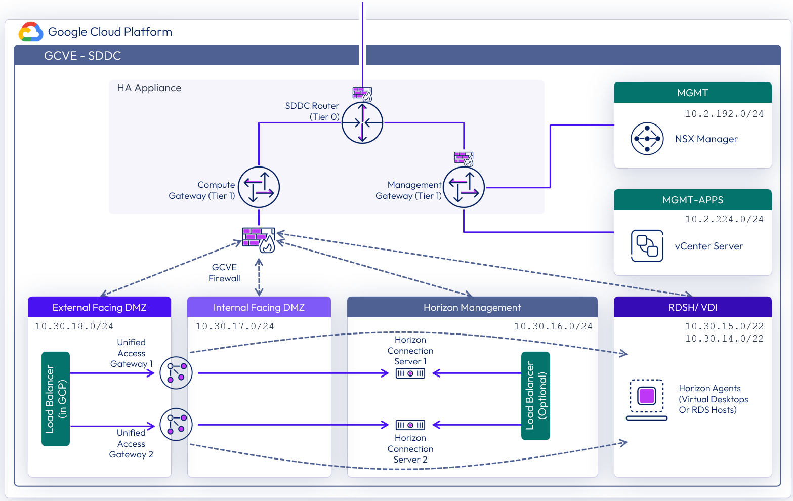
Figure 14: Network diagram with All-In-SDDC architecture (subnets are for illustrative purposes only)
Federated architecture networking
In the federated architecture, all of the Horizon management components including the Unified Access Gateway appliances are located inside of GCP. This allows the use of multiple GCVE SDDC as a target for capacity for desktops / RDS hosts. In the Federated Architecture, you will need to create a subnet for the Horizon Management components in a VPC network. You will also need to create new VPC networks for the Internal and External DMZ networks to use with the Unified Access Gateways. See Horizon 8 on Google Cloud VMware Engine Configuration for details.
- NSX - desktop / RDS segments with DHCP enabled
- Subnet in Google Cloud Platform VPC network for Horizon management components
- Omnissa Horizon Connection Servers
- Omnissa Unified Access Gateway - deployed as two-NIC
- Omnissa App Volumes Managers
- File Server
- Database Server
- Omnissa Workspace ONE Connector
- Omnissa Horizon Edge Gateway appliance (used when connecting to Horizon Cloud Service – next-gen)
- New VPC Network for internal DMZ
- New VPC Network for external DMZ
The following diagram illustrates the network design of the federated architecture.
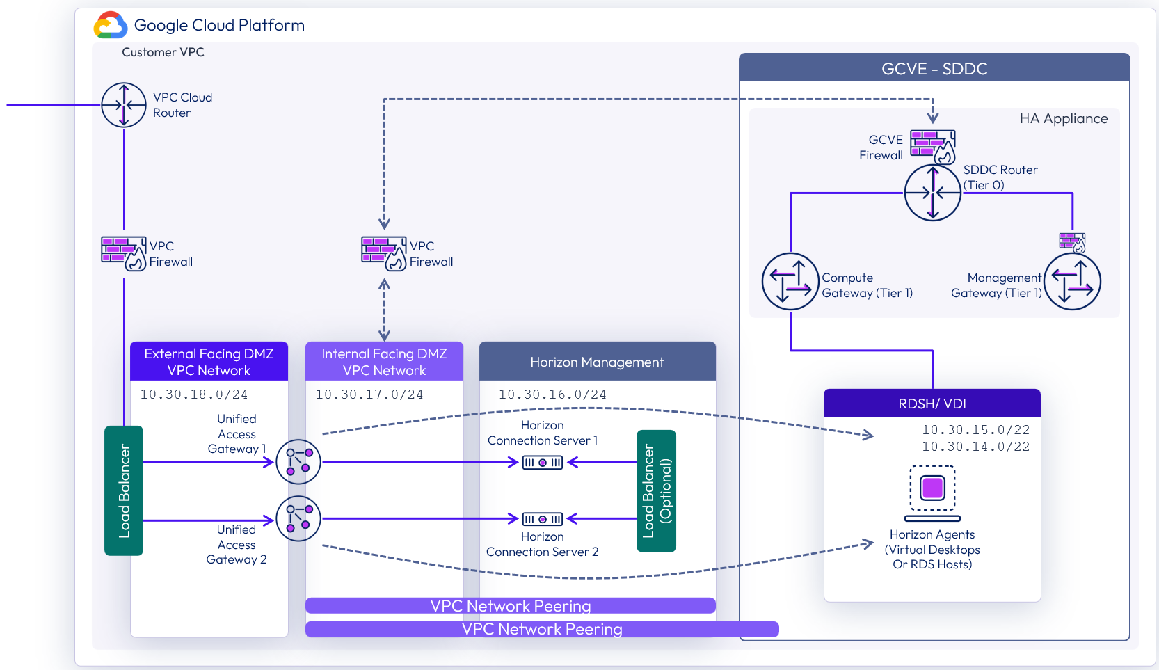
Figure 15: Network diagram with federated architecture (subnets are for illustrative purposes only)
Load balancing Unified Access Gateway appliances
To ensure redundancy and scale, multiple Unified Access Gateways are deployed. To implement them in a highly available configuration and provide a single namespace, a third-party load balancer, such as the Google Load Balancer or the NSX Advanced Load Balancer (Avi) can be used. A minimum of two Unified Access gateways should be deployed in a two-NIC (double DMZ) configuration. See Two-NIC Deployment in the Unified Access Gateway Architecture chapter for details. To provide direct external access, a public IP address would be configured forward traffic to the load balancer virtual IP address. In the All-in-SDDC architecture a third-party load balancer is required to forward Horizon protocol traffic into the Unified Access Gateways located inside the SDDC.
Unified Access Gateway deployment in the All-in-SDDC architecture
In the All-in-SDDC Architecture, the Unified Access Gateway appliances are located inside of the GCVE SDDC. There is no way to forward Horizon protocol traffic from the Google Load Balancer into the Unified Access Gateways inside of the SDDC. In this case, you will need a third-party load balancer located in GCP. The Google Load Balancer would have forwarding rules to send TCP and UDP to the third-party load balancer, which would be configured to load balance the Unified Access Gateways inside of GCVE. See the Horizon 8 on Google Cloud VMware Engine Configuration document for information on configuring protocol traffic forwarding. See Load Balancing Unified Access Gateway in Horizon 8 Architecture for details on load balancing the UAG appliances.
In this configuration, an internal and external DMZ segment should be created in GCVE with the following firewall rules:
- Internal DMZ – Access to segments containing desktops, connection servers, and DNS
- External DMZ – Access to the segment in GCP containing the third-party load balancer used for forwarding Horizon protocol traffic
Static routes might be needed on the Unified Access Gateway as follows:
- Internal DMZ (NIC 2) – Static route to segments containing desktops and the connection servers
- External DMZ (NIC 1) – Static route to segments in GCP containing the third-party load balancer used for forwarding Horizon protocol traffic
Table 2: Load balancing strategy for Unified Access Gateways in the All-in-SDDC architecture
| Decision | A third-party load balancer was used to load balance the Unified Access Gateways. The NSX Advanced load balancer was used. |
| Justification | A load balancer enables the deployment of multiple management components, such as Unified Access Gateways, to allow scale and redundancy. A third-party load balancer is required to route protocol traffic into the SDDC from GCP. The NSX Advanced load balancer was used as it integrates with Google Cloud Platform for orchestration. |
Unified Access Gateway deployment in the federated architecture
In this architecture, the Unified Access Gateway appliances are located directly in GCP, which eliminates the need to place a third-party load balancer to forward protocol traffic into the SDDC. As of Unified Access Gateway 2103, running the UAG appliances directly inside of GCP is supported. See the Deploying Unified Access Gateway on Google Cloud for details on deployment of UAG into GCP.
In this configuration, Internal and External DMZ VPC networks should be created in GCP with the following VPC Peering and firewall rules:
- Internal DMZ – Access to segments (VPC Peering) containing desktops, connection servers, and DNS
- External DMZ – Access to third party load balancer (if used). If using the built-in Google load balancer, this VPC network needs no peering configured.
Static routes might be needed on the Unified Access Gateway as follows:
- Internal DMZ (NIC 2) – Static route to segments containing desktops and the connection servers
See Network Settings for details on setting static routes in Unified Access Gateway. See Horizon 8 on Google Cloud VMware Engine Configuration for details on setting up the VPC networks for UAG and on configuring the Google Load Balancer for use with UAG.
Table 3: Load balancing strategy for Unified Access Gateways in the federated architecture
| Decision | A third-party load balancer was used to load balance the Unified Access Gateways. The Google Cloud Platform Load Balancer was used. |
| Justification | A load balancer enables the deployment of multiple management components, such as Unified Access Gateways, to allow scale and redundancy. The Google Cloud Platform load balancer can load balance the Unified Access Gateway appliances in GCP. |
Load balancing Connection Servers
Multiple Horizon Connection Servers are deployed for scale and redundancy. Depending on the user connectivity, you may or may not need to deploy a third-party load balancer to provide a single namespace for the Connection Servers. When all user connections originate externally and come through a Unified Access Gateway, it is not necessary to have a load balancer between the Unified Access Gateways and the Connection Servers. Each Unified Access Gateway can be defined with a specific Connection server as its destination.
While the diagram below shows a 1 to 1 mapping of Unified Access Gateway to Connection Server, it is also possible to have a N to 1 mapping, where more than one Unified Access Gateway maps to the same Connection Server.
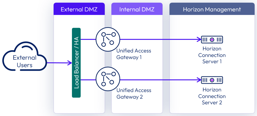
Figure 16: Load balancing when all connections originate externally
Where users will be connecting from internally routed networks and their session will not go via a Unified Access Gateway, a load balancer should be used to present a single namespace for the Connection Servers. A load balancer such as the Google Load Balancer or NSX Advanced Load Balancer (Avi), should be deployed. See the Load Balancing Connection Servers section of the Horizon 8 Architecture chapter.
When required for internally routed connections, a load balancer for the Connection Servers can be either:
- Placed in between the Unified Access Gateways and the Connection Server and used as an FQDN target for both internal users and the Unified Access Gateways.
- Located so that only the internal users use it as an FQDN.
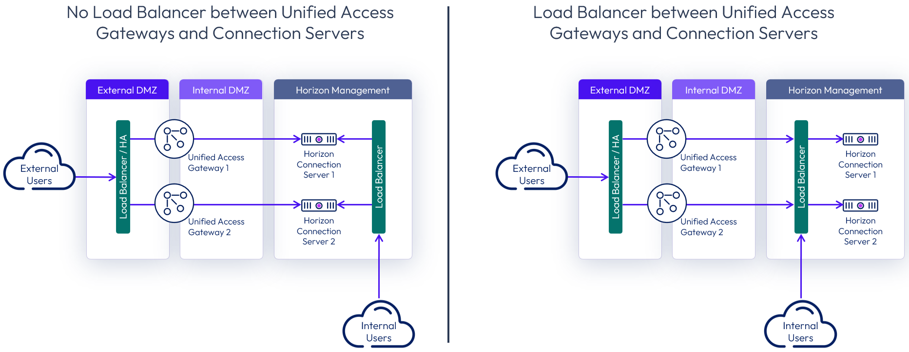
Figure 17: Options for load balancing Connection Servers for internal connections
An example of internal users in this use case would be users connecting through Direct Connect, via a Shared VPC or via VPN with split-DNS. So, the same namespace (desktops.company.com) would resolve externally to the public IP address in GCP and internally to the internal load balancer.
Table 4: Load balancing Connection Servers strategy
| Decision | Connection Servers were not load balanced. |
| Justification | All the users will connect to the environment externally. |
External networking
When direct external access is required, configure a public IP address in GCP that will be bound to a public DNS entry; for example, desktops.company.com.
- In the All-In-SDDC Architecture, this IP address would use GCP forwarding rules to send TCP and UPD traffic to the third-party load balancer, which would be load-balancing the Unified Access Gateway appliances located inside of each SDDC.
- In the Federated Architecture, the external IP address would be assigned to a GCP load balancer front-end for TCP and UPD, which would point to the Unified Access Gateway appliances in GCP as a back-end resource.
See Horizon 8 on Google Cloud VMware Engine Configuration for details on how to configure this.
For external management or access to external resources, create a VPN or direct connection within GCP, and do this in the Networking | Hybrid Connectivity section of the GCP console. See Google Cloud How-to guides for details.
DHCP service
It is critical to ensure that all VDI enabled desktops have properly assigned IP addresses. In most cases, you would opt for automatic IP assignment.
Horizon 8 on GCVE supports assigning IP addresses to clients as follows:
- NSX based local DHCP service, attached to the Compute Gateway (default).
Table 5: DHCP Service Strategy both All-in-SDDC and Federated Architectures
| Decision | NSX was used to provide DHCP assigned IP addresses for desktops. |
| Justification | This provided properly assigned IP address and integrates directly into Horizon. |
DNS service
Reliable and correctly configured name resolution is vital for a successful Horizon deployment. While designing your environment, make sure you understand Configuring DNS for Management Appliance Access. Your design choice will directly influence the configuration details.
- It is recommended to use local DNS Server (hosted on GCVE or GCP) to reduce dependency on the connection link to on-premises.
- For a single GCVE SDDC, you can use a conditional forwarder in your DNS server for gve.goog pointing to the IP addresses of the DNS servers in the SDDC.
- For multiple GCVE SDDCs with the Federated Architecture, you need to use a DNS forward lookup zone for gce.goog, which contains the fully qualified domain names and IP address of the vCenter and NSX appliances.
- See Configure DNS for more information.
Important: If you are deploying more than one SDDC in GCVE for use with Horizon 8, make sure to use unique CIDR for the management components. By default, they use the same CIDR and have the same IP addresses. If you don’t change this default, you will not be able to use the multiple vCenters with Horizon. For more information, see the GCVE documentation on setting up a private cloud.
Table 6: DNS strategy for a single SDDC
| Decision | Add the DNS role to a local Domain Controller located in GCVE. Configure DNS Conditional forwarding for gce.goog. |
| Justification | The local DNS server allows local name resolution without depending on a connection to on-premises. Since only one SDDC is used, the conditional forwarder for gve.goog pointing to the DNS servers in that SDDC can be used. |
Table 7: DNS strategy for multiple SDDCs
| Decision | Add the DNS role to a local Domain Controller located in GCP. Create forward lookup zone for gve.goog. |
| Justification | The local DNS server allows local name resolution without depending on a connection to on-premises. Since we have more than one SDDC defined, we need to create a forward lookup zone for gve.goog. |
Scaling deployments
In this section, we will discuss scaling options for scaling out Horizon on GCVE. Following are the design decisions for both the All-in-SDDC and Federated Architectures.
All-in-SDDC - single SDDC
This design is comprised of a single SDDC which will handle up to approximately 4,000 concurrent Horizon users. There will be a single FQDN (desktops.customer.com) bound to a public IP address. A third-party load balancer is used to forward Horizon protocol traffic to the Unified Access Gateway appliances located inside of the SDDC. Users will use the desktops.customer.com FQDN via the Horizon Client, HTML access or it will automatically be used with Omnissa Access integration. The following figure is a logical view of the All-in-SDDC Architecture showing all the Horizon components (Management and User Resources) located inside of the SDDC.
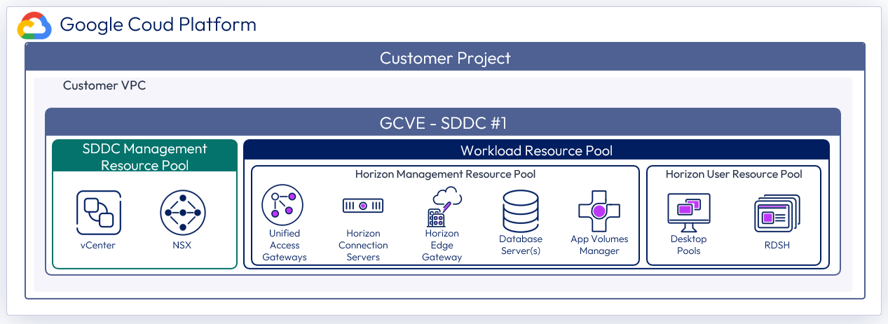
Figure 18: Logical architecture for a single SDDC with the All-in-SDDC architecture
The figure below illustrates the collection flow with a single SDDC using the All-in-SDDC Architecture. Since there is no way to get Horizon protocol traffic directly from the Internet to the Unified Access Gateways located in the SDDC, we need to use a third-party load balancer. The Google Load balancer forwards tcp/upd from the public IP to a pool containing the third-party load balancer which is configured to load balance the Unified Access Gateways located inside of the GCVE SDDC.

Figure 19: Horizon connection flow with single SDDC using the All-in-SDDC architecture
The figure below shows the All-in-SDDC architecture, with all networking done via NSX inside the SDDC and the third-party load balancer located in GCP to forward Horizon protocol traffic.
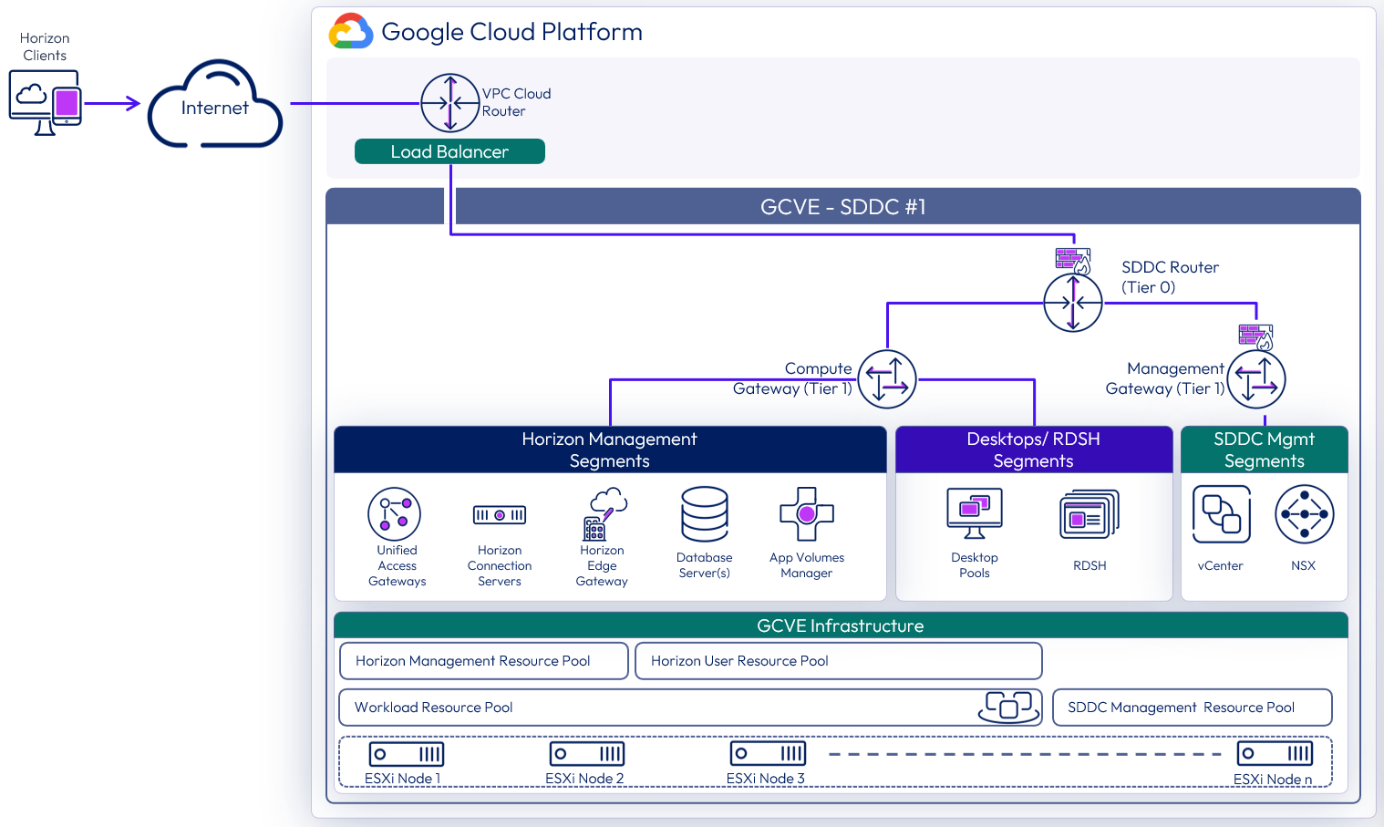
Figure 20: All-in-SDDC architecture with a single SDDC with networking
Table 8: Connection Server strategy for the All-in-SDDC architecture
| Decision | Two connection servers were deployed. These ran on dedicated Windows Servers VMs located in the internal network segment within the SDDC. |
| Justification | One Connection Server supports a maximum of 4,000 sessions. A second server provides redundancy and availability (n+1). |
Table 9: Unified Access Gateway strategy for the All-in-SDDC architecture
| Decision | Two standard-size Unified Access Gateway appliances were deployed inside a GVCE SDDC as part of the Horizon All-in-SDDC Architecture. These spanned the Internal and External DMZ networks. |
| Justification | Unified Access Gateway provides secure external access to internally hosted Horizon desktops and applications. One standard Unified Access Gateway appliance is recommended for up to 2,000 concurrent Horizon connections. A second Unified Access Gateway provides redundancy and availability (n+1). |
Table 10: App Volumes Manager strategy for the All-in-SDDC architecture
| Decision | Two App Volumes Managers were deployed. The two App Volumes Managers are load balanced with the NSX Advanced (Avi) load balancer in GCP. |
| Justification | App Volumes is used to deploy applications locally. The two App Volumes Managers provide scale and redundancy. |
Table 11: Workspace ONE Access Connector strategy for the All-in-SDDC architecture
| Decision | Two Workspace ONE Access connectors were deployed. |
| Justification | To connect back to our Workspace ONE instance to integrate entitlements and allow for seamless brokering into desktops and applications. Two connectors deployed for resiliency. |
Table 12: Dynamic Environment Manager strategy for the All-in-SDDC architecture
| Decision | Dynamic Environment Manager (DEM) was deployed on the local file server. |
| Justification | This is used to provide customization / configuration of the Horizon desktops. This location contains the Configuration and local Profile shares for DEM. |
Table 13: SQL Server strategy for the All-in-SDDC architecture
| Decision | A single SQL server was deployed. |
| Justification | This SQL server was used for the Horizon Events Database and App Volumes. |
Table 14: Load balancing strategy for the All-in-SDDC architecture
| Decision | A third-party load balancer was used to load balance the Unified Access Gateways and App Volumes Managers. |
| Justification | A load balancer enables the deployment of multiple management components, such as Unified Access Gateways, to allow scale and redundancy. A load balancer is required to route protocol traffic into the SDDC from GCP. |
All-in-SDDC - multiple SDDCs
As the All-in-SDDC architecture for Horizon 8 in GCVE places all the management components inside each SDDC, there are some considerations when scaling above a single SDDC.
- Each SDDC hosts a separate Horizon pod each with their own set of Horizon Connection Servers.
- Each pod requires a separate FQDN and can be addressed separately.
- Cloud Pod Architecture is not recommended with the All-in-SDDC Architecture.
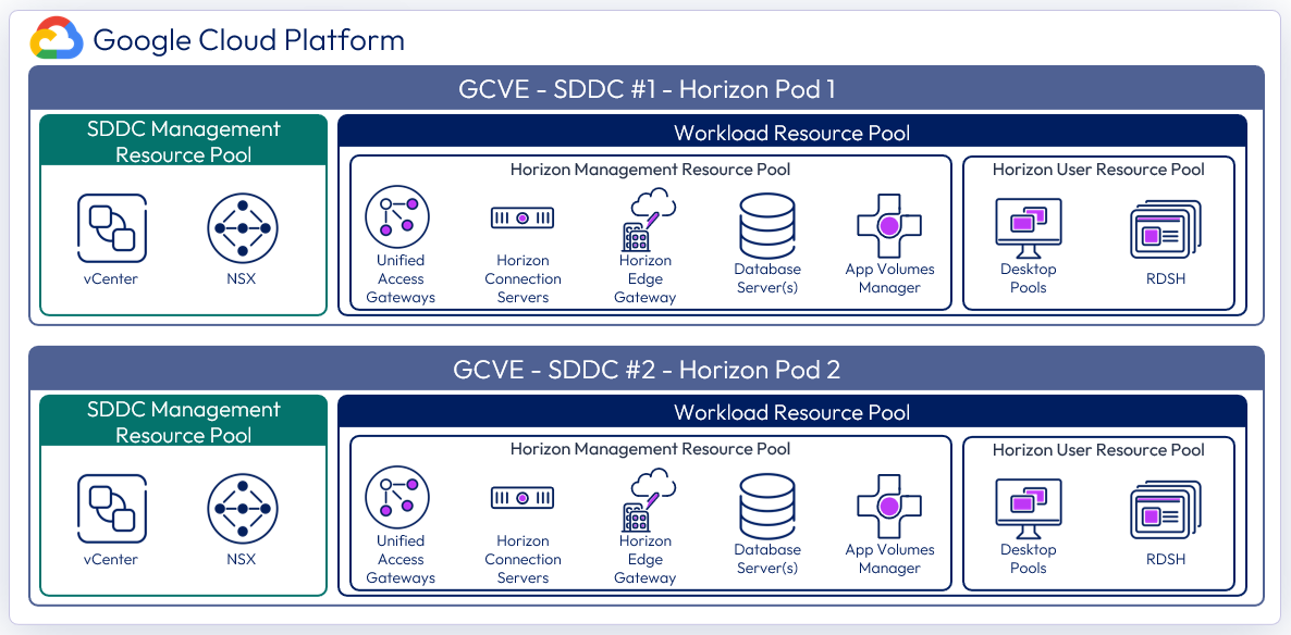
Figure 21: Logical architecture for the All-in-SDDC architecture with multiple SDDCs
With the All-in-SDDC architecture, the key recommendation is that a Horizon pod should only contain a single GCVE SDDC. As mentioned earlier, each pod will have a dedicated FQDN for user access. For example, desktops1.company.com and desktops2.company.com. Each pod/SDDC would have a dedicated external IP address that would tie to its FQDN.
As illustrated in the figure below, users’ sessions would be directed to a particular Horizon pod and therefore the SDDC that hosts that pod. This avoids the possibility of protocol traffic hairpinning through one SDDC to get to the destination SDDC.
Universal Broker, or Workspace ONE Access can be used to provides a single FQDN for user logon. This would then direct the user’s session to the correct individual Horizon pod’s FQDN where their chosen resources are located. Alternatively, users could just directly connect to individual pods using the Horizon Client, although that requires the user to choose the correct pod for the desired resource.
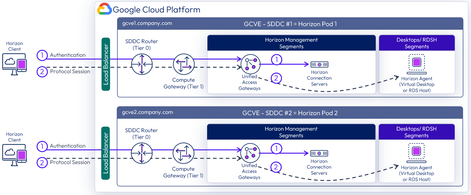
Figure 22: Horizon connection flow for All-in-SDDC architecture with multiple SDDCs
As in the single All-in-SDDC design, all of the Horizon components are located inside each SDDC, and a third-party load balancer is located in GCP that forwards Horizon protocol traffic to the Unified Access Gateways for each respective Horizon pod.
The figure below shows the All-in-SDDC architecture, with all networking done via NSX inside the SDDC and the third-party load balancer located in GCP to forward Horizon protocol traffic. This load balancer will be configured with the public IP addresses of both SDDCs and will load balance the Unified Access Gateway appliances located in each SDDC.
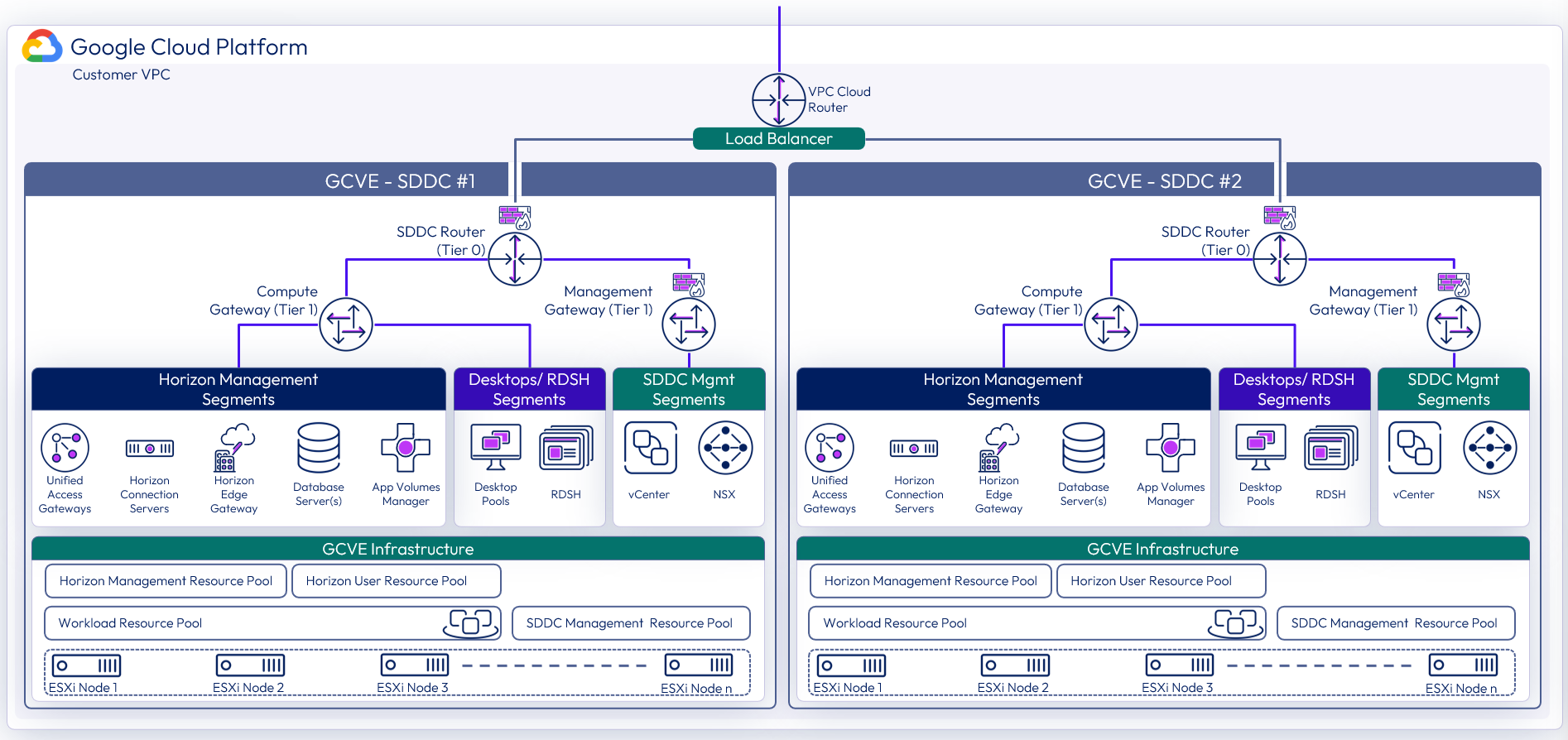
Figure 23: All-in-SDDC architecture with two SDDCs and networking
Federated architecture
In the Federated architecture, all of the Horizon management components are located inside of native GCP. There is still a guidance of approximately 4,000 concurrent connections per SDDC, but the federated architecture allows you to create a Horizon pod consisting of multiple SDDCs. This solution is architected the same way that on-premises Horizon is architected, and the front-end management components would just need to be scaled to handle the concurrent connections from the back end GCVE desktop resources.
See Omnissa Configuration Maximums or product documentation for the version of Horizon 8 you are deploying for the maximums of the Horizon components. Once DNS resolution is set up as described in DNS service in this document, you can simply add the additional vCenter Servers in Horizon. You will notice in the following figure that the Deployment Type shows as GCVE.

Figure 24: Two vCenter Servers from two GCVE SDDCs in the federated architecture added to Horizon
The figure below illustrates the federated architecture with all of the Horizon components located inside of GCP, and multiple SDDCs used for desktop/RDS capacity to create a Horizon pod. In the federated architecture, a single Horizon pod would be comprised of one or more SDDCs, and scaled up to Horizon maximums for the pod. Currently, a single Horizon pod can contain up to five (5) vCenter Servers and therefore five GCVE SDDCs for desktop/RDS capacity. Beyond this, a new Horizon pod should be created with new Horizon management components. The two can be joined into a federation with cloud pod architecture and global entitlements can be used.
In this example diagram below, the four SDDCs could be sized for up to 16,000 concurrent connections with the front-end Horizon management components sized accordingly.
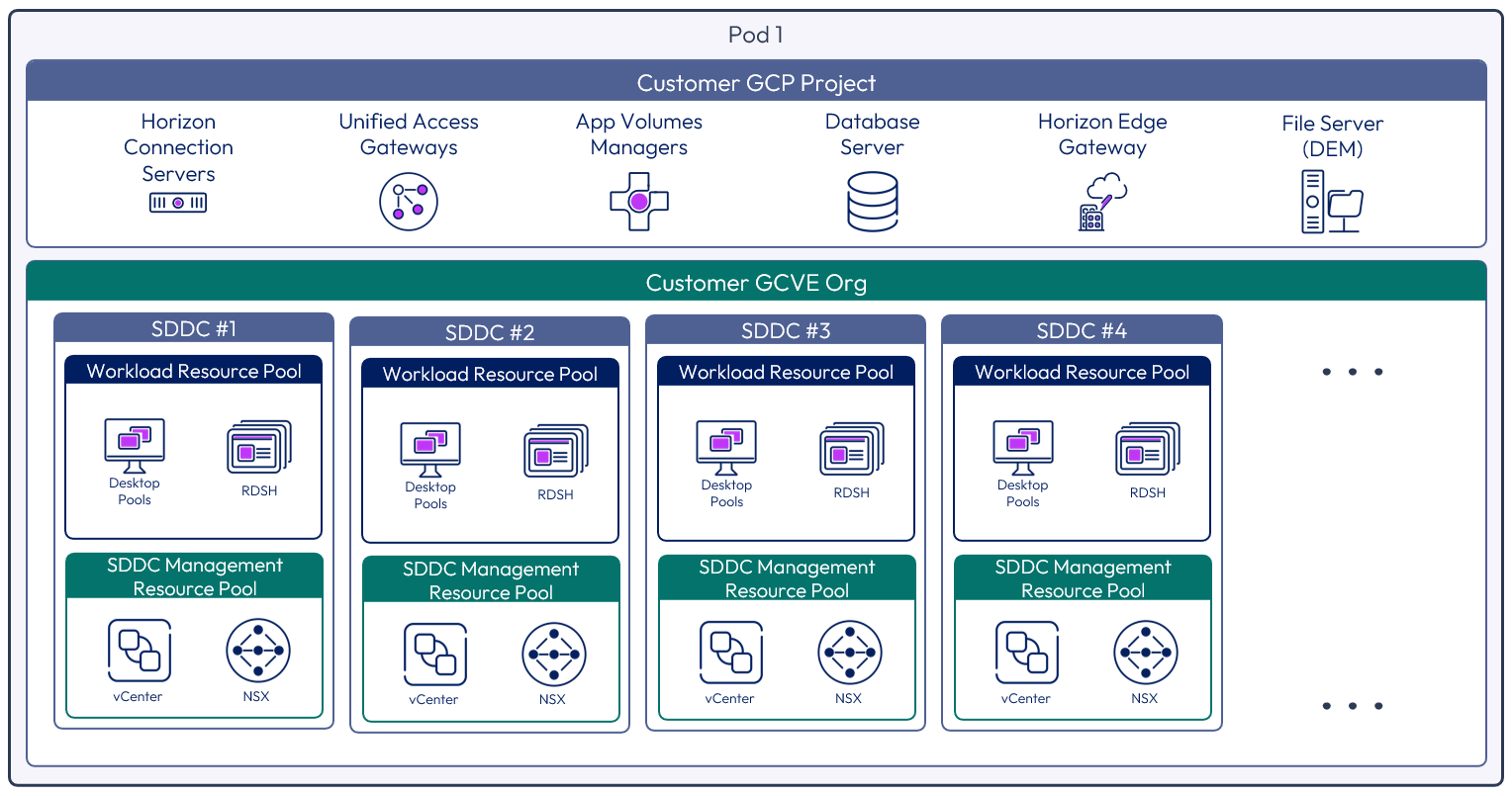
Figure 25: Multiple GCVE SDDCs within one Horizon pod using the Horizon federated architecture
The following figure illustrates the connection flow for a user. They would connect via the FQDN, which would then go to the Google Load Balancer in GCP hosting the public IP. This is set up to load balance the Unified Access Gateway appliances. The user would be challenged for authentication by one of the Unified Access Gateways via a Connection Server, and then once authenticated, a Horizon protocol session would be established to the desktop or published application in one of the SDDCs in the Horizon pod.
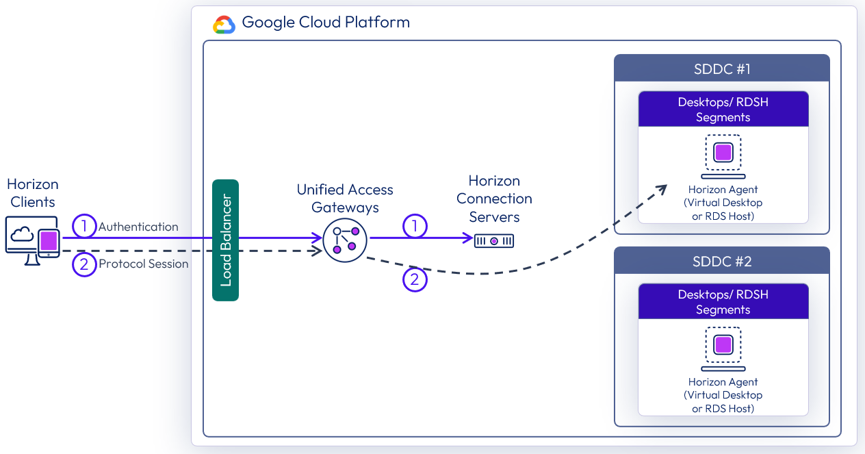
Figure 26: Traffic flow with multiple GCVE SDDCs using the federated architecture
The figure below illustrates the federated architecture with the Horizon pod management resources located in GCP and the desktop/RDS resources scaled out into multiple SDDCs. Networking is done both in the GCP VPC and inside the GCVE SDDC with NSX for the desktop/RDS segments.
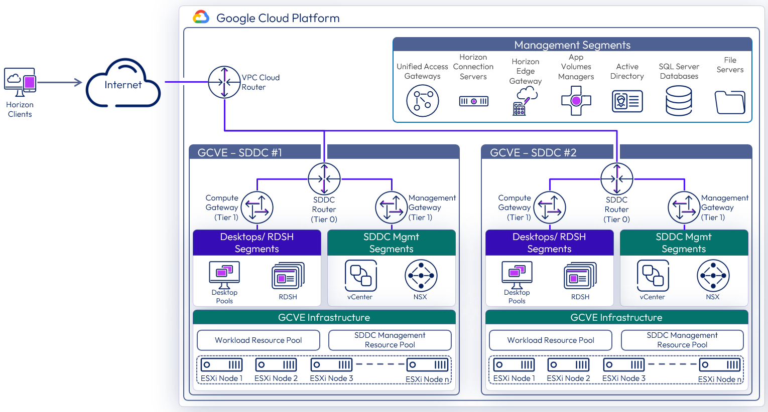
Figure 27: Federated architecture with two SDDCs networking
Table 15: SDDC strategy for the federated architecture
| Decision | |
| Justification | This allowed testing of the federated architecture with the Horizon management components located in GCP and the Desktop/RDS resources located in vCenters located in two separate SDDCs. |
Table 16: Connection Server strategy for the federated architecture
| Decision | Three Horizon Connection Servers were deployed. These ran on dedicated Windows Server VMs located in the GCP Management network. |
| Justification | One Connection Server supports a maximum of 4,000 sessions. A second server provides redundancy and availability (n+1). |
Table 17: Unified Access Gateway strategy for the federated architecture
| Decision | Four standard-size Unified Access Gateway appliances were deployed as part of the Horizon solution. These spanned the Internal and External DMZ VPC networks. |
| Justification | Unified Access Gateway provides secure external access to internally hosted Horizon desktops and applications. One standard UAG appliance is recommended for up to 2,000 concurrent Horizon connections. With no load balancer inline between the UAGs and the Connection Server each UAG targets a particular Connection Server. To match up with the requirement for two Connection Servers, we should look to have a 2 to 1 ratio or UAG to Connection Server. This leads to an overall count of four UAGs, to ensure redundancy and availability. |
Table 18: App Volumes Manager strategy for the federated architecture
| Decision | Three App Volumes Managers were deployed. The three App Volumes Managers are load balanced with the built-in load balancer in GCP. |
| Justification | App Volumes is used to deploy applications locally. The three App Volumes Managers provide scale and redundancy. |
Table 19: Workspace ONE Access Connector strategy for the federated architecture
| Decision | Two Workspace ONE Access connectors were deployed. |
| Justification | To connect back to our Workspace ONE instance to integrate entitlements and allow for seamless brokering into desktops and applications. Two connectors were deployed for resiliency. |
Table 20: Dynamic Environment Manager strategy for the federated architecture
| Decision | Dynamic Environment Manager (DEM) was deployed on the local file server. |
| Justification | This is used to provide customization / configuration of the Horizon desktops. This location contains the Configuration and local Profile shares for DEM. |
Table 21: SQL Server strategy for the federated architecture
| Decision | A single SQL server was deployed. |
| Justification | This SQL server was used for the shared App Volumes database. |
Table 22: PostgreSQL Server strategy for the federated architecture
| Decision | A single PostgreSQL server 12.x was deployed. |
| Justification | This PostgreSQL server was used for the Horizon Events Database. |
Table 23: Load balancing strategy for the federated architecture
| Decision | A load balancer was used to load balance the Unified Access Gateways and App Volumes Managers. The Google Load Balancer was used. |
| Justification | A load balancer enables the deployment of multiple management components, such as Unified Access Gateways, to allow scale and redundancy. |
Multiple Horizon pods
When deploying environments with multiple Horizon pods, there are different options available for administrating and entitling users to resources across the pods. This is applicable for Horizon environments on GCVE, on other cloud platforms, or on-premises.
- The Horizon pods can be managed separately, users entitled separately to each pod, and users directed to the use the unique FQDN for the correct pod.
- Using Omnissa Access, Horizon entitlements and resources from multiple Horizon pods and environments can be presented in one place to the users.
- Alternatively, you can manage and entitle the Horizon environments by linking them using Cloud Pod Architecture (CPA).
- Important: CPA is not recommended in GCVE with the All-in-SDDC architecture.
Protocol traffic hairpinning
If the authentication traffic is not precisely directed, by using a unique namespace for each Horizon Pod, the user could be directed to any Horizon pod in its respective SDDC. If the user’s Horizon resource is not in that SDDC where they are initially directed to for authentication, their Horizon protocol traffic would go into the initial SDDC to a Unified Access Gateway in that SDDC and then back out via the NSX edge gateways and then be directed to where their desktop or published application is being delivered from.
This causes a reduction in achievable scale due to this protocol hairpinning. For this reason, Cloud Pod Architecture is not recommended in the All-In-SDDC Architecture and caution should be exercised if using Cloud Pod Architecture in the Federated Design. If you create a Cloud Pod Federation that contains both a Horizon pod on-premises and a Horizon pod in GCVE, you could run into a similar issue where the user gets directed to one pod which does not contain their assigned resource and then would be routed back out to the other pod. This flow is illustrated in the following diagram.
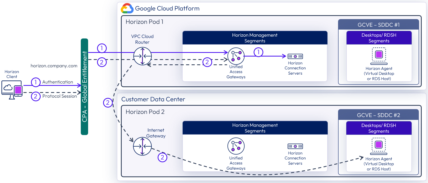
Figure 28: Horizon protocol traffic hairpinning with federated design (UAGs in GCP)
Networking to on-premises
With Horizon on GCVE, you can connect your on-premises environments to allow the use of resources such as Horizon Cloud Pod Architecture (Federated Architecture option only), to expand your Active Directory into the GCVE environment, or replicate Dynamic Environment Manager data. Either a Cloud Interconnect or a Cloud VPN can be established between on-premises sites and GCP.
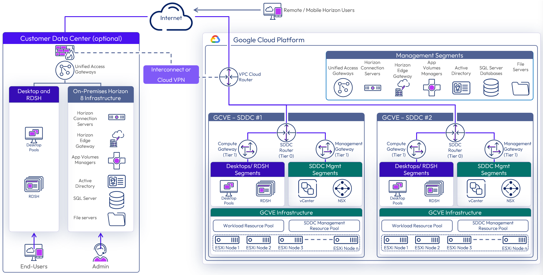
Figure 29: GCVE federated architecture with networking to on-premises
Table 24: Virtual Private Network strategy
| Decision | A Virtual Private Network (VPN) was established between GCP and our on-premises environment. |
| Justification | Allow for extension of on-premises services into the GCP/GCVE environment. |
Table 25: Domain Controller strategy
| Decision | A single domain controller was deployed as a member of on-premises domain. This domain controller is used as a DNS server for the SDDC. |
| Justification | A site was created to keep authentication traffic local to the site. This allows Group Policy settings to be applied locally. This allows for local DNS queries. In the event of an issue with the local domain controller, authentication requests can traverse the VPN back to our on-premises domain controllers. |
Table 26: File Server strategy
| Decision | A single file server was deployed with DFS-R replication to on-premises file servers. |
| Justification | General file services for the local site. Allow the common Dynamic Environment Manager configuration data to be replicated to this site. Keep the profile data for Dynamic Environment Manager local to the site, with a backup to on-premises. |
Licensing
Enabling Horizon 8 to run on GCVE requires a Horizon subscription license. This license does not include GCVE, and this must be purchased separately from Google.
To enable the use of subscription licensing, each Horizon 8 pod must be connected to the Horizon Cloud Service. For more information on how to do this, see the Horizon Cloud Service section of the Horizon 8 Architecture chapter.
For a POC or pilot deployment of Horizon 8 on GCVE, you can use a temporary evaluation license or your existing perpetual license. However, to enable Horizon for production deployment on GCVE, you must purchase a Horizon subscription license. For more information on the features and packaging of Horizon subscription licenses.
You can use different licenses (including perpetual licenses) on different Horizon 8 pods, regardless of whether the pods are connected by CPA. You cannot mix different licenses within a pod because each pod only takes one type of license. For example, you cannot use both a perpetual license and a subscription license for a single pod. You also cannot use both the Horizon Apps Universal Subscription license and the Horizon Universal Subscription license in a single pod.
Preparing Active Directory
Horizon requires Active Directory services. For supported Active Directory Domain Services (AD DS) domain functional levels, see the Knowledge Base (KB) article: Supported Operating Systems, Microsoft Active Directory Domain Functional Levels, and Events Databases for Omnissa Horizon 8 (78652).
If you are deploying Horizon 8 in a hybrid cloud environment by linking an on-premises environment with an GCVE Horizon pod, you should extend the on-premises Microsoft Active Directory (AD) to GCP or GCVE.
Although you could access on-premises active directory services and not locate new domain controllers in GCP/GCVE, this could introduce undesirable latency, service resiliency, or availability.
A site should be created in Active Directory Sites and Services and defined to the subnets containing the Domain Controller(s) for GCP/GCVE. This will keep the active directory services traffic local.
Table 27: Active Directory strategy
| Decision | An Active Directory domain controller was installed into GCP. |
| Justification | Locating domain controllers in GCP reduces latency for Active Directory queries, DNS, and KMS. |
Shared content library
Content libraries are container objects for VM, vApp, and OVF templates and other types of files, such as templates, ISO images, text files, and so on. vSphere administrators can use the templates in the library to deploy virtual machines and vApps in the vSphere inventory. Sharing golden images across multiple vCenter Server instances, between multiple GCVE and/or on-premises SDDCs guarantees consistency, compliance, efficiency, and automation in deploying workloads at scale.
For more information, see Using Content Libraries in the vSphere Virtual Machine Administration documentation.
Resource sizing
When resource sizing, make sure to take memory, CPU, and VM-level reservations into consideration, as well as leveraging CPU shares for different workloads.
Memory reservations
Because physical memory cannot be shared between virtual machines, and because swapping or ballooning should be avoided at all costs, be sure to reserve all memory for all Horizon virtual machines, including management components, virtual desktops, and RDS hosts.
CPU reservations
CPU reservations are shared when not used, and a reservation specifies the guaranteed minimum allocation for a virtual machine. For the management components, the reservations should equal the number of vCPUs times the CPU frequency. Any amount of CPU reservations not actively used by the management components will still be available for virtual desktops and RDS hosts when they are not deployed to a separate cluster.
Virtual machine–level reservations
As well as setting a reservation on the resource pool, be sure to set a reservation at the virtual machine level. This ensures that any VMs that might later get added to the resource pool will not consume resources that are reserved and required for HA failover. These VM-level reservations do not remove the requirement for reservations on the resource pool. Because VM-level reservations are taken into account only when a VM is powered on, the reservation could be taken by other VMs when one VM is powered off temporarily.
Leveraging CPU shares for different workloads
Because RDS hosts can facilitate more users per vCPU than virtual desktops can, a higher share should be given to them. When desktop VMs and RDS host VMs are run on the same cluster, the share allocation should be adjusted to ensure relative prioritization.
Deploying desktops
With Horizon 8 on GCVE both instant clones and full clones can be used. Instant clones, coupled with App Volumes and Dynamic Environment Manager helps accelerate the delivery of user-customized and fully personalized desktops.
Connection Server
When deploying the first Connection Server in the SDDC, make sure to choose “Google Cloud” as the deployment type. This sets the proper configuration and permissions on the Connection Server and Virtual Center.
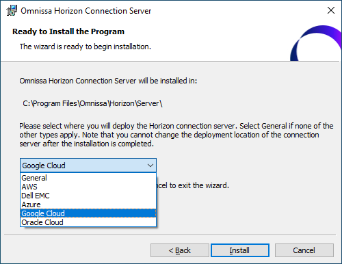
Figure 31: Horizon Deployment Methods Option
At the time of writing, Horizon 8 (2006) and later, and Horizon 7.13 are supported on GCVE. For details on supported features, see the KB: Horizon on Google Cloud VMware Engine (GCVE) Support (81922).
Instant clones
Dramatically reduce infrastructure requirements while enhancing security by delivering brand-new personalized desktop and application services to end users every time they log in:
- Reap the economic benefits of stateless, non-persistent virtual desktops served up to date upon each login.
- Deliver a pristine, high-performance personalized desktop every time a user logs in.
- Improve security by destroying desktops every time a user logs out.
- On the golden image VM, add the domain’s DNS to avoid customization failures.
When you install and configure Horizon for instant clone for deployment on GCVE, do the following:
Important: CBRC is not supported or needed on GCVE. CBRC is not turned off when deploying Horizon on GCVE. Do NOT enable CBRC on vCenter when creating an Instant Clone Pool. You may see this message when creating an Instant Clone pool because CBRC is turned off on vCenter.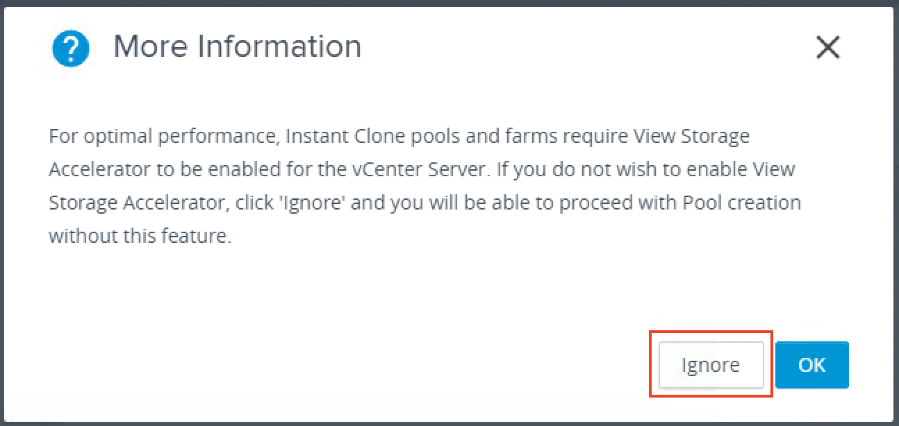
Figure 32: Warning about turning on View Storage Accelerator (CBRC)
Make sure to choose Ignore on this dialog message.
Multi-VLAN is not yet supported when creating Horizon instant-clone pools on GCVE.
For more information on Instant clones, see Instant Clone Smart Provisioning.
App Volumes
Omnissa App Volumes provides real-time application delivery and management, for on-premises and now on GCVE:
- Quickly provisions applications at scale
- Dynamically attaches applications to users, groups, or devices, even when users are already logged in to their desktop
- Provisions, delivers, updates, and retires applications in real time
- Provides a user-writable volume, allowing users to install applications that follow them across desktops
- Provides end users with quick access to a Windows workspace and applications, with a personalized and consistent experience across devices and locations
- Simplifies end-user profile management by providing organizations with a single and scalable solution that leverages the existing infrastructure
- Speeds up the login process by applying configuration and environment settings in an asynchronous process instead of all at login
- Provides a dynamic environment configuration, such as drive or printer mappings, when a user launches an application
For design guidance, see App Volumes Architecture.
Dynamic Environment Manager
Use Omnissa Dynamic Environment Manager for application personalization and dynamic policy configuration across any virtual, physical, and cloud-based environment. Install and configure Dynamic Environment Manager on GCVE just like you would install it on-premises.
Summary and additional resources
Now that you have come to the end of this design chapter on Omnissa Horizon 8 on GCVE, you can return to the reference architecture landing page and use the tabs, search, or scroll to select further chapter in one of the following sections:
- Overview chapters provide understanding of business drivers, use cases, and service definitions.
- Architecture chapters give design guidance on the Omnissa products you are interested in including in your deployment, including Workspace ONE UEM, Access, Intelligence, Workspace ONE Assist, Horizon Cloud Service, Horizon 8, App Volumes, Dynamic Environment Manager, and Unified Access Gateway.
- Integration chapters cover the integration of products, components, and services you need to create the environment capable of delivering the services that you want to deliver to your users.
- Configuration chapters provide reference for specific tasks as you deploy your environment, such as installation, deployment, and configuration processes for Omnissa Workspace ONE, Horizon Cloud Service, Horizon 8, App Volumes, Dynamic Environment Management, and more.
Additional resources
For more information about Omnissa Horizon 8 on GCVE, you can explore the following resources:
Changelog
The following updates were made to this guide:
| Date | Description of Changes |
| 2025-04-01 |
|
| 2025-01-13 |
|
| 2024-05-27 |
|
| 2023-07-19 |
|
| 2022-10-20 |
|
| 2022-09-08 |
|
| 2021-12-16 |
|
Author and contributors
This chapter was written by:
- Chris Halstead, Senior Staff Technical Product Manager, Omnissa.
- Graeme Gordon, Senior Staff Architect, Omnissa.
Feedback
Your feedback is valuable. To comment on this paper, either use the feedback button or contact us at tech_content_feedback@omnissa.com.

