Horizon 8 on Google Cloud VMware Engine configuration
This chapter is one of a series that make up the Omnissa Workspace ONE and Horizon Reference Architecture, a framework that provides guidance on the architecture, design considerations, and deployment of Omnissa Workspace ONE and Omnissa Horizon solutions. This chapter provides information about common configuration and deployment tasks for Omnissa Horizon 8 on Google Cloud VMware Engine (referred to as GCVE throughout this document).
A companion chapter, Horizon 8 on Google Cloud VMware Engine Architecture, provides design guidance.
Prerequisites
Before you begin, you must install and configure the following components:
- GCVE resources assigned to you
- Google Cloud login
- Omnissa Horizon Universal Licensing with access to customerconnect.omnissa.com, required to set up licensing on the Horizon Edge Gateway.
- If deploying Horizon with the All-in-SDDC architecture:
- Third-party load balancer to install into GCP to forward Horizon protocol traffic from GCP to GCVE
You should also review the following documentation:
Google Cloud Platform configuration
This section covers configuration of the Google Cloud Platform (GCP) to prepare for Horizon installation. This information is provided as reference and the official Google docs should be used for your actual configuration.
See the following guides to help you get started:
Following are the steps we went through when creating the Reference Architecture environment. Your configuration might vary, this information is provided as reference. Rely on the official Google quick-start guides referenced previously for your actual configuration.
Google Cloud Console
To get to the Google cloud console, where both Google Cloud Platform and GCVE are managed, go to https://console.cloud.google.com/
Create VPC network
The first step is to create a Virtual Private Cloud which will contain the networks for your implementation. See Google Cloud VPC Networking Overview for more information.
- On the GCP Menu, in the Networking section, select VPC Network > VPC Networks.
- Click Create VPC Network on the top.
- Enter the subnet details to create the VPC network:
| Field | Value |
| Name | **name of network** |
| Description | **description** |
| Subnet Creation Mode | Custom |
| New Subnet > Name | **name of subnet** |
| New Subnet > Region | **GCP region** |
| New Subnet > IP Address Range | Example: 10.20.0.0/24 (GW: 10.20.0.1) |
| New Subnet > Private Google Access | Off |
| New Subnet > Flow Logs | Off |
| Dynamic Routing Mode | Regional |
Configure VPC / GCVE private service connection
A private service connection must be established between any VPC network that needs access to GCVE (for example, Internal DMZ VPC). Additionally, any subnets created inside of GCVE must be manually allocated to allow communication between the GCP and GCVE environments.
See the following documents for more details:
- GCVE Documentation for setting up a private service connection and allocating IP ranges
- GCVE Prerequisites
- Configuring private services access
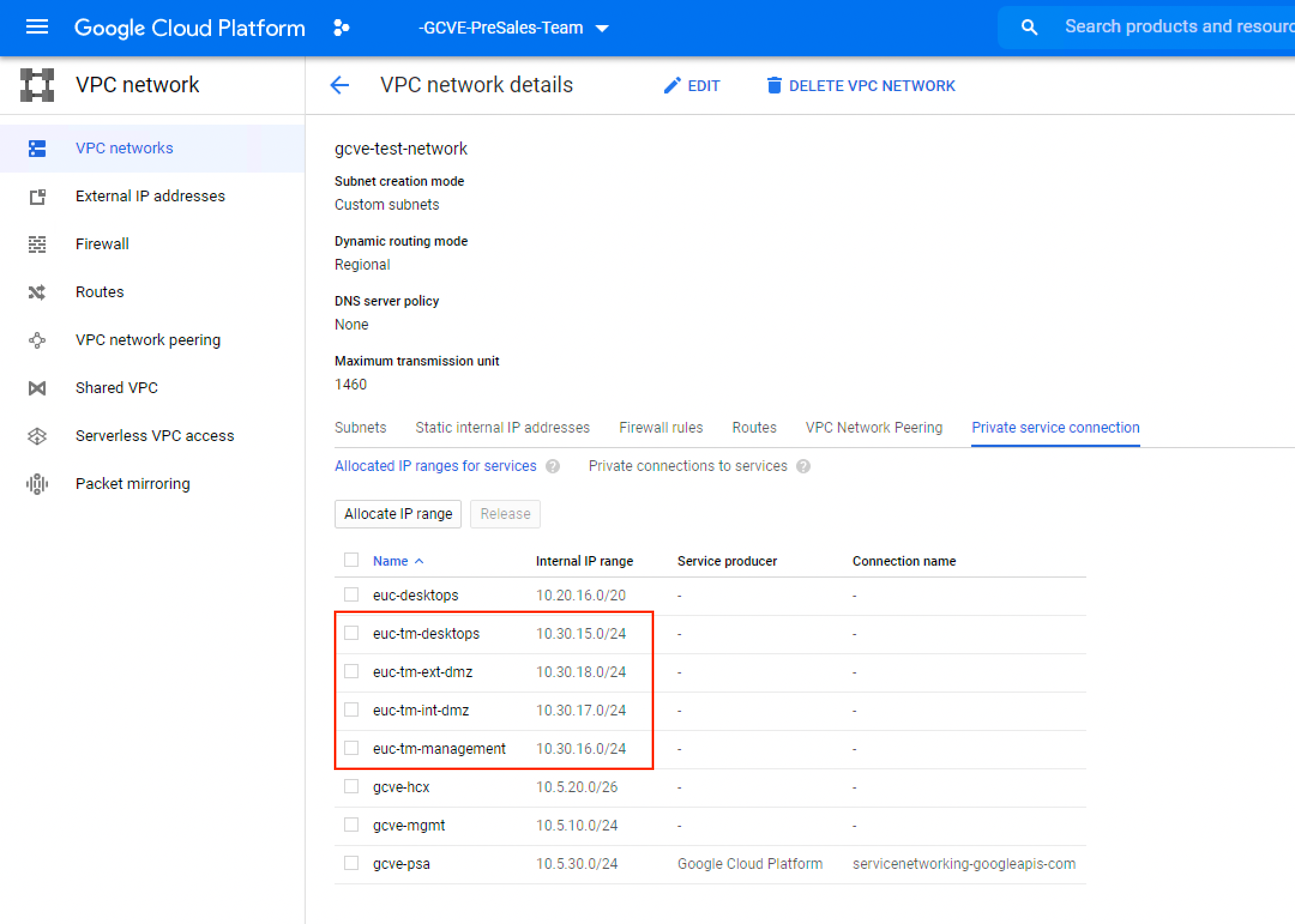
Figure 1: VPC Network Private Service connection
Important: After you create segments in NSX for the Horizon infrastructure, you must come back to this section and add those subnets for them to communicate with GCP.
Create firewall rules in GCP
Note that by default, they are set to deny all. Make sure to set the ports required for Horizon on both the GCVE Firewall and the VPC Firewall.
- Navigate to VPC Network > VPC Networks > **VPC network you created**.
- Select the Firewall rules tab.
- Click Add firewall rule and add a rule for each subnet created in GCVE to allow traffic to flow in and out of GCP. After segments are created in GCVE, new firewall rules in GCP must be added.
- Refer to Network Ports in Horizon 8 for required Horizon ports.
Note: Depending on setup and network requirements, we also recommend creating a firewall rule for the entire range assigned to GCVE. For example, instead of creating multiple /24 rules, create a /22 rule.
See the Google Cloud Platform documentation on setting firewall rules in GCP.
Enable cloud NAT for internet access
Enable Cloud NAT for your VPC to allow internet access. See Using Cloud NAT for details.
Deploy Unified Access Gateway in GCP
In the Federated Architecture of Horizon on GCVE, the Unified Access Gateways (UAG) are in GCP. This prevents Horizon protocol hair-pinning which could happen when the UAG is placed inside the SDDC. This is supported as of UAG 2103. See Deploying Unified Access Gateway on Google Cloud for guidance.
Deploy the Horizon Cloud Connector into GCP
Note: New Horizon 8 pods should be connected to Horizon Cloud Service – next-gen using the Horizon Edge Gateway appliance. The guidance on installing that in GCP is not currently covered in this guide.
As of Horizon 2103, the Horizon Cloud Connector is supported for installation into GCP using version 1.10 or later. There is a disk.raw version zipped as a tar.gz file. This is a requirement for importing an existing image into GCP. See the Google documentation on importing existing image.
For the latest guidance on sizing the Horizon Cloud Connector when deploying on GCVE, see Horizon 8 Pods with First-Gen Horizon Control Plane - Requirements Checklist - Starting November 2, 2023.
After you deploy the cloud connector image, and before you start it up the first time, you will need to create a startup script on the VM to update the hosts files with the names of your connection servers and virtual centers. It should look like the image below. After you have started up the system and bound your cloud connector to the Horizon Control Plane, you can delete the startup script.

Figure 2: GCP Startup script used on first startup of Horizon Cloud Connector
VPC peering
When a Virtual Private Cloud (VPC) network is created, it is essentially an island. There is no connectivity by default to other VPC networks. We need to use VPC Peering to connect two separate VPC networks and allow them to communicate internally. See the Google documentation on VPC Peering for an overview and Using VCP Network Peering for directions on configuration. We need to use VPC peering in the Federated Architecture to connect the Internal DMZ network used for UAG to the VPC network where the Horizon management components are located. A private service connection between the Internal DMZ VPC and each GCVE SDDC where desktop and RDS capacity will be used. See Network Configuration for more details on networking requirements.

Figure 3: Horizon on GCVE federated architecture networking
GCVE configuration
This section covers configuration of the GCVE environment to prepare for Horizon installation. This information is provided as reference and the official Google docs should be used for your actual configuration.
To get to the GCVE console:
- In the GCVE console, browse to Compute in the GCP menu and select VMware Engine.

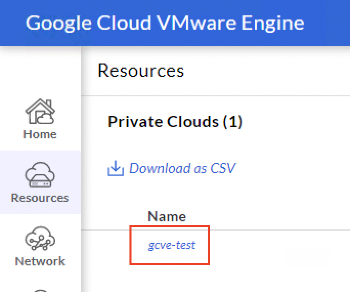
- In the GCVE console, select Resources and then select the name of your private cloud.

- Now, select Summary and make note of the Private Cloud DNS Server addresses, which are required for setting up conditional forwarding.

Deploying multiple GCVE SDDCs
When you deploy additional SDDCs in GCVE make sure to use unique CIDR ranges (a method for IP addresses and routing) for the Management Network. Otherwise with the default settings, each vSphere / NSX server will have the same IP address and you will not be able to use them with Horizon. See How to Create a Private Cloud for details.
Configure DNS
You must define settings on your DNS server for gve.goog pointing to the IP addresses of the Private Cloud DNS servers captured in the previous step, or create a forward lookup zone for gve.goog. This will allow name resolution for the vCenter and NSX appliances.
Single GCVE SDDC:
For this design, you can use a conditional forwarder to have your local DNS server use the DNS servers in the SDDC to do name lookup of management appliances. See Create a Conditional Forwarder for details.
Multiple GCVE SDDCs:
When multiple SDDCs are deployed, you cannot use a conditional forwarder. One way to accomplish the name resolution needed by Horizon is to create a forward lookup zone for gve.goog in the DNS server you are using for your Horizon infrastructure.
![]()
Figure 4: vCenter and NSX Manager FQDNs in GCVE Admin Console
You would add A records for the fully qualified names and IPs of each vCenter and NSX appliance.

Figure 5: gve.goog forward lookup zone in DNS
See Configuring DNS for vCenter access for more details on the process.
NSX
Networking for your SDDC must be created in the NSX admin console. When you are in the GCVE management console, select vSphere Management Network, and then click the link for the NSX Manager under FQDN.

Figure 6: NSX Manager FQDN in GCVE admin console
- Log in to the NSX Manager using the default login credentials:
- Username:
admin - Password:
VMwareEngine123!
- Create segments for Desktops, Management, and Internal and External DMZ.
- Enable DHCP on the desktops segment and optionally the management segment.
- See the NSX Installation Guide for more information on how this is done.
- Update the GCVE Firewall for communication to/from GCP for newly created segments.
vSphere console
In the same section that the NSX console was launched, you can launch the vSphere console. This is where the Horizon infrastructure is created and managed.
- Click the link under FQDN for the vCenter Server appliance.

- Log in to vCenter using the default login:
- Username:
CloudOwner@gve.local - Password:
VMwareEngine123!
External access
Optionally, set up VPN or Cloud Interconnect for backhaul to on-premises. In this reference architecture, we created a VPN connection from GCP back to our on-premises data center. This allowed us to extend our domain into the GCVE environment and provide file server replication via DFS-R for Dynamic Environment Manager.
See the following documents for configuring external access into GCP:
Load balancing in the All-In-SDDC architecture
If deploying the All-in-SDDC architecture where all Horizon resources, including the Unified Access Gateways, are located in the GCVE SDDC, there is no way to directly route Horizon protocol traffic from GCP into the SDDC. We need a load balancer in native GCP to forward the protocol traffic from the Internet to the UAGs inside of the GCVE SDDC.
One option is to use the Avi Load Balancer on GCP, which can integrate with GCP via a cloud integration and perform all these configurations automatically.
Additionally, see Load Balancing Unified Access Gateway in Horizon 8 Architecture.
Forwarding traffic to third-party load balancer in GCP
A third-party load balancer is required inside of GCP to route protocol traffic into the SDDC. It can be any type of load balancer which does HTTP, Layer 4, and Layer 7 load balancing. If the load balancer does not have integration with GCP like the NSX Advanced load balancer does, some manual steps are required to forward the external IP address into the load balancer. The GCP Load Balancer needs to be configured to forward TCP and UDP from the public IP address that is tied to your FQDN to the third-party load balancer. These steps are detailed below.
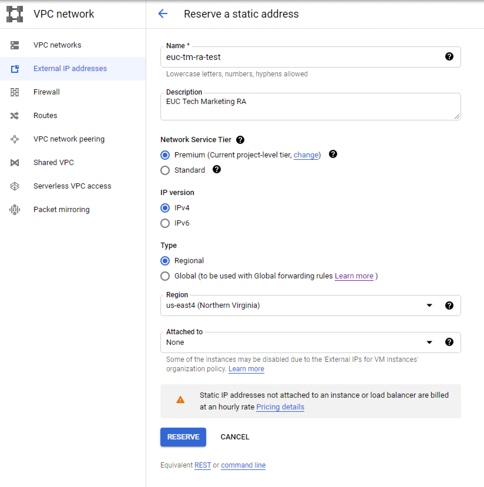
Create static external IP address
First, we will create a static external IP address inside the GCP VPC networking. This IP will be used by the load balancer and should be assigned a public DNS entry for users to connect to desktop resources. For example, gcve-horizon.domain.com.
- Go to VPC network > External IP Addresses.

- Note the External IP address. You will need it in the next steps.
Create load balancer in GCP
We will now create a load balancer in GCP that will be used to forward external traffic (TCP/UDP) from the external IP address to our third-party load balancer. We cannot use the GCP load balancer for systems inside GCVE, so we need to use the third-party load balancer.
Before you perform this step, your third-party load balancer should be installed into native GCP.
- Navigate to Networking > Network Services in the GCP Console.
- Select Load Balancing.
- Navigate to the Advanced Menu.


Create target pool
- Create a target pool to put the third-party load balancer into.

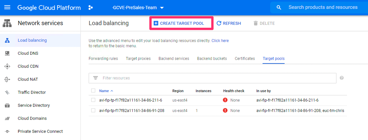
- Configure the target pool by providing the following information:

- Provide a name and description.
- Select the GCP region where your load balancer is located.
- Select No health check.
- Select None for session affinity.
- Add your existing load balancer instances from GCP into the pool (can be multiple).
- Select None for Backup pool.
- Click Create.
Create TCP forwarding rule
We will now create forwarding rules, to forward TCP and UDP traffic from the external IP address to the pool we just created.
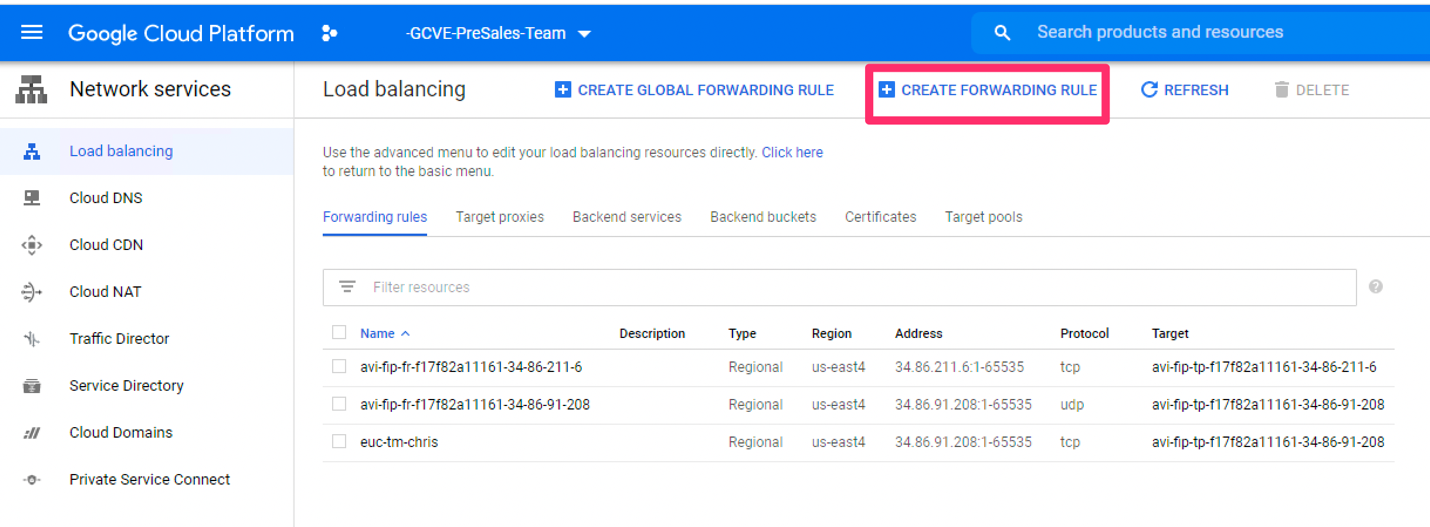
- Click Create Forwarding Rule to start creating the TCP forwarding rule.


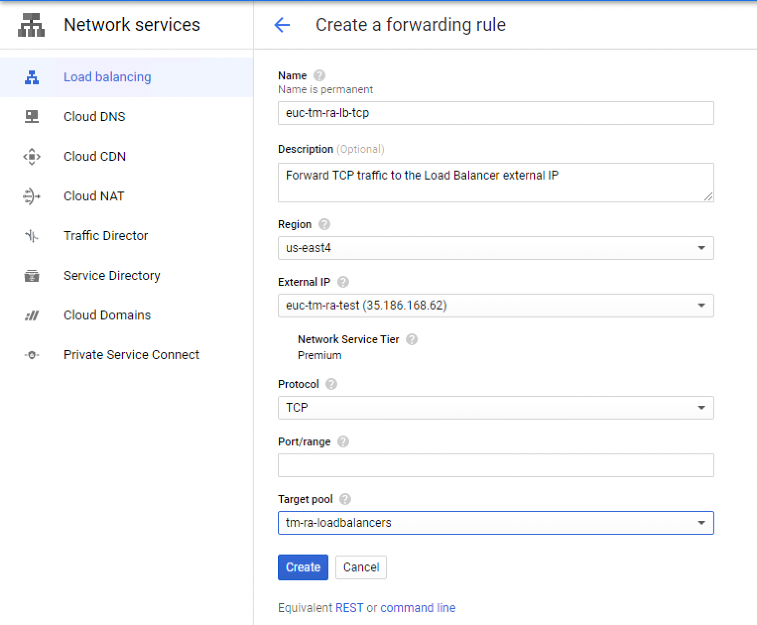
- Configure the TCP forwarding rule by providing the following information:

- Enter a name and description (add the protocol being forwarded).
- Select the region where your load balancers are.
- Select the external IP you created earlier.
- Select the protocol as TCP.
- Leave Port/range blank to forward all rules.
- Select the target pool you created in the previous step containing your load balancer(s).
Create UDP forwarding rule
- Create a second forwarding rule for UDP.
- Enter a name and description and include UDP in the name.
- Select the region where your load balancers are located.
- Select the external IP you created earlier.
- Select UDP as the protocol.
- Leave the Port range blank to forward all UDP traffic.
- Select the pool you created earlier containing your load balancers.

- Review the load balancer forwarding rules that were created.
Review load balancer and external IP
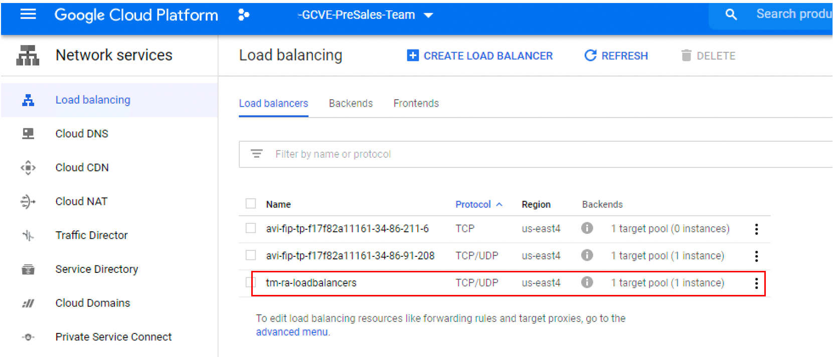
If you select Load Balancing, you will see a new TCP/UDP load balancer created to forward external traffic to your load balancers.
- Navigate to VPC network > External IP Addresses.
![]()
- Review the external IP Address you just created for the load balancer created in GCP. It will now have the forwarding rules attached to it for TCP and UDP.

Load balancing in the federated architecture
In the Federated Architecture, the Google Load Balancer can be used to load balance the Unified Access Gateway appliances. There is no need for a third-party load balancer like in the All-in-SDDC Architecture.
Create static external IP address
First, we will create a static external IP address inside the GCP VPC networking. This IP will be used by the load balancer and should be assigned a public DNS entry for users to connect to desktop resources. For example, desktops.company.com.
- Go to VPC network > External IP Addresses.

- Note the External IP address. You will need it in the next steps.
Create load balancer in GCP
We will now create a load balancer in GCP that will be used to forward external traffic (TCP/UDP) from the external IP address to our third-party load balancer.
Before you perform this step, your third-party load balancer should be installed into native GCP.
- Navigate to Networking > Network Services in the GCP Console.
- Select Load Balancing.
- Navigate to the Advanced Menu.


Create target pool
We now need to create a target pool to put Unified Access Gateways into.
- Click Create Target Pool.

- Configure the target pool by providing the following information:

- Provide a name and description.
- Select the GCP region where your load balancer is located.
- Select Create Another Health Check (See Create Health Check).
- Select Client IP for session affinity.
- Add your existing Unified Access Gateway appliances from GCP into the pool.
- Select None for Backup pool.
- Click Create.
Create health check
To create a Health Check for Unified Access Gateways:
- Provide the following information:
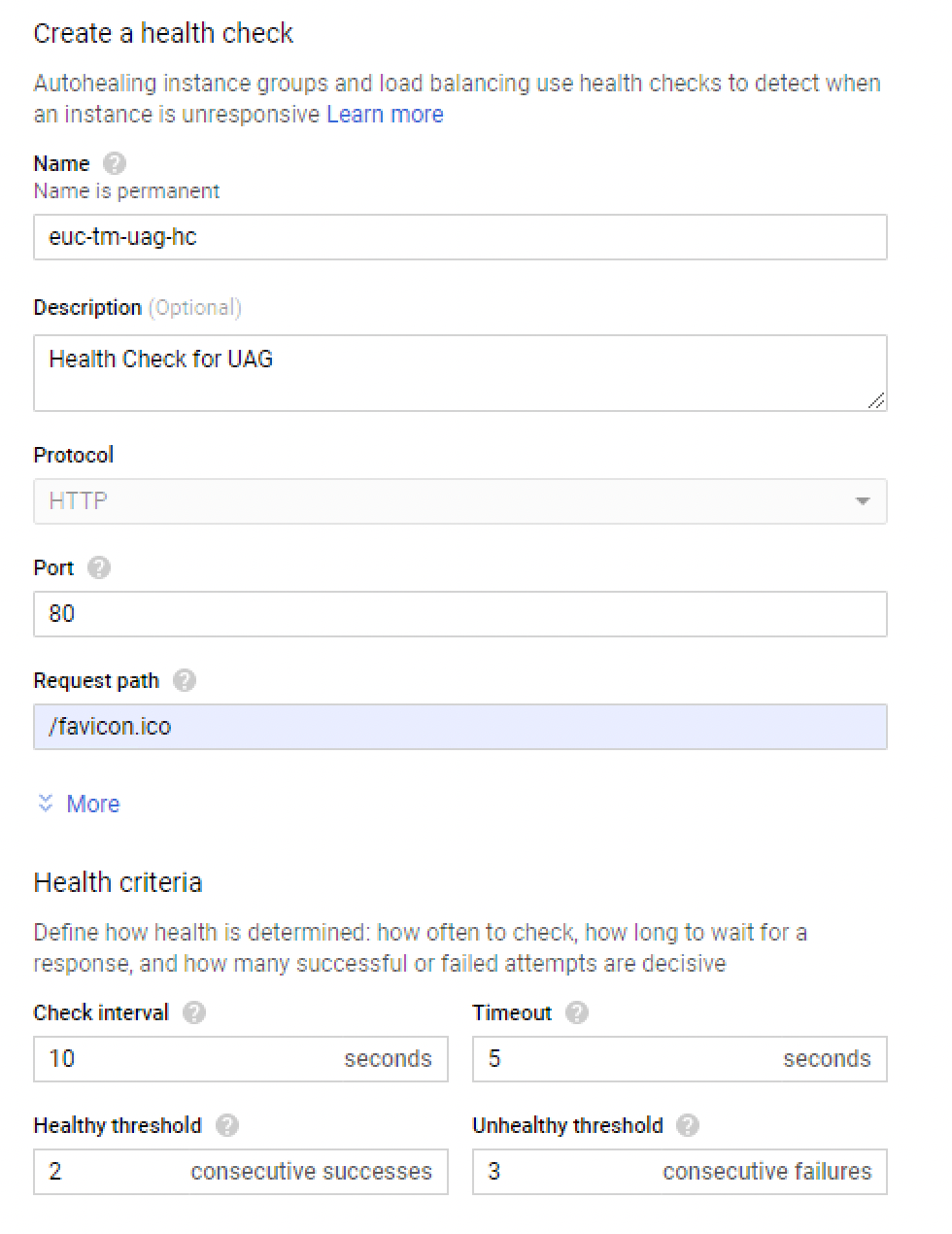
- Enter a name and optional description.
- Select HTTP for the Protocol.
- Set the Port as 80.
- Set the Request Path as /favicon.ico.
- Leave the defaults for Heath criteria.
Important: You will need to update each UAG appliance to use the http health check under System Configuration.
Figure 7: Health Check Configuration on Unified Access Gateway
Create TCP forwarding rule
We will now create forwarding rules to forward TCP and UDP traffic from the external IP address to the pool we just created.
- Click Create Forwarding Rule to create the TCP forwarding rule in GCP.

- Configure the forwarding rule in GCP by providing the following information:

- Enter a name and description (add the protocol being forwarded).
- Select the GCP region where your UAG appliances are located.
- Select the external IP you created earlier.
- Select the protocol as TCP.
- Leave Port/range blank to forward all rules.
- Select the target pool you created in the previous step containing your UAG appliances.
Create UDP forwarding rule
- Create a second forwarding rule for UDP.
- Enter a name and description and include UDP in the name.
- Select the GCP region where your UAG appliances are located.
- Select the external IP you created earlier.
- Select UDP as the protocol.
- Leave the Port range blank to forward all UDP traffic.
- Select the pool you created earlier containing your UAG appliances.
- Review the load balancer forwarding rules that were created.

Review load balancer and external IP
If you select Load Balancing, you will see a new TCP/UDP load balancer created to forward external traffic to your UAG appliances.
- Navigate to VPC network > External IP Addresses and review the External IP Address you just created.


- It will now have the forwarding rules attached to it for TCP and UDP.

Inventory
This section includes the inventory of the All-in-SDDC architecture and Federated architecture.
All-In-SDDC architecture
This section provides the inventory of infrastructure installed in the Reference Architecture lab, deployed both inside native Google Cloud Platform and inside GCVE SDDC, for All-in SDDC architecture.
Deployed inside native Google Cloud Platform:
| Component | Version | Operating System | Number Deployed |
| NSX Advanced Load Balancer (Avi) Controller | 20.1.2 | CentOS 7.5 (Docker) | 1 |
| NSX Advanced Load Balancer (Avi) Service Engine | 20.1.2 | Appliance | 2 |
Deployed inside GCVE SDDC:
| Component | Version | Operating System | Number Deployed |
| Horizon Connection Server | Version 8 (2006) | Windows Server 2019 | 2 |
| Unified Access Gateway | 2006 | Appliance | 2 |
| App Volumes Managers | Version 4.1 (2006) | Windows Server 2019 | 2 |
| Horizon Cloud Connector | 1.8 | Appliance | 1 |
| Workspace ONE Access Connector | 19.03 | Windows Server 2019 | 1 |
| Microsoft SQL Server | 2016 | Windows Server 2019 | 1 |
| File Server | - | Windows Server 2019 | 1 |
| Domain Controller | - | Windows Server 2019 | 1 |
Federated architecture
This section provides the inventory of infrastructure installed in the Reference Architecture Lab deployed inside native Google Cloud Platform for federated architecture.
For instruction on deploying Windows Server VMs into Google Cloud Platform see Create a Windows Server VM instance in Compute Engine.
Deployed inside native Google Cloud Platform:
| Component | Version | Operating System | Number Deployed |
| Horizon Connection Server | Version 8 (2103) | Windows Server 2019 | 3 |
| Unified Access Gateway | 2103 | Appliance | 3 |
| App Volumes Managers | Version 4.4 (2103) | Windows Server 2019 | 3 |
| Horizon Cloud Connector | 1.10 | Appliance | 2 |
| Workspace ONE Access Connector | 19.03 | Windows Server 2019 | 1 |
| Microsoft SQL Server | 2016 | Windows Server 2019 | 1 |
| PostgreSQL Server | 12.6 | Windows Server 2019 | 1 |
| File Server | - | Windows Server 2019 | 1 |
Summary and additional resources
Now that you have come to the end of this configuration chapter on Omnissa Horizon 8 on GCVE, you can return to the reference architecture landing page and use the tabs, search, or scroll to select further chapter in one of the following sections:
- Overview chapters provide understanding of business drivers, use cases, and service definitions.
- Architecture chapters give design guidance on the Omnissa products you are interested in including in your deployment, including Workspace ONE UEM, Access, Intelligence, Workspace ONE Assist, Horizon Cloud Service, Horizon 8, App Volumes, Dynamic Environment Manager, and Unified Access Gateway.
- Integration chapters cover the integration of products, components, and services you need to create the environment capable of delivering the services that you want to deliver to your users.
- Configuration chapters provide reference for specific tasks as you deploy your environment, such as installation, deployment, and configuration processes for Omnissa Workspace ONE, Horizon Cloud Service, Horizon 8, App Volumes, Dynamic Environment Management, and more.
Additional resources
For more information about deploying Horizon 8 on GCVE, you can explore the following resources:
Changelog
The following updates were made to this guide:
| Date | Description of Changes |
| 2025-04-01 |
|
| 2025-01-14 |
|
| 2024-06-04 |
|
| 2023-07-25 |
|
Author and contributors
This chapter was written by:
- Chris Halstead, Senior Staff Technical Product Manager, Omnissa.
Feedback
Your feedback is valuable. To comment on this paper, either use the feedback button or contact us at tech_content_feedback@omnissa.com.


