

Configuring High Availability in Unified Access Gateway
Overview
Omnissa provides this operational tutorial to help you with your Omnissa Workspace ONE and Omnissa Horizon environments.
This tutorial guides you through the deployment of two Unified Access Gateway appliances and the setup of high availability in both. High availability for Unified Access Gateway simplifies your deployment by removing the need for a third-party load balancer in front of the Unified Access Gateway appliances.
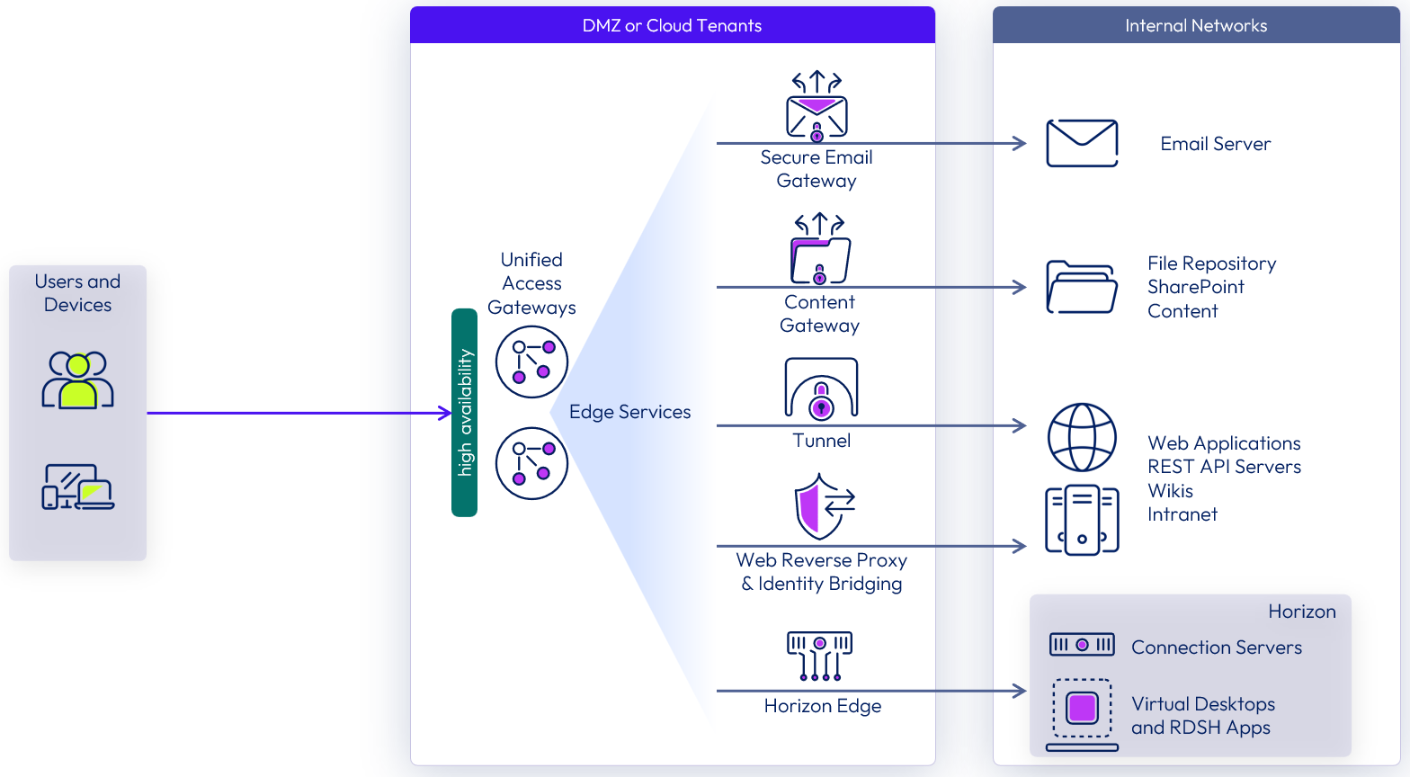
Figure 1: Unified Access Gateway logical architecture overview
You will learn how to deploy two appliances, creating a cluster with high availability configured, identify how Unified Access Gateway sets appliances in the cluster as the primary and backup appliances, and test the failover of the high availability component from one appliance to another.
Before starting this tutorial, it is recommended that you review the architecture of high availability deployments of Unified Access Gateway.
Audience
This operational tutorial is intended for IT professionals and Workspace ONE UEM or Horizon administrators of existing production environments.
Unified Access Gateway high availability
Unified Access Gateway high availability supports up to 10,000 concurrent connections in the cluster using a combination of traffic distribution methods:
- Source IP affinity — Maintains the affinity between the client connection and Unified Access Gateway node. All connections with the same source IP address are sent to the same Unified Access Gateway node.
- Round robin mode with high availability — Distributes incoming connection requests across the group of Unified Access Gateway nodes sequentially. When the Unified Access Gateway holding the virtual IP address fails, the virtual IP address is reassigned automatically to one of the nodes available in the cluster. The high availability and load distribution occurs among the nodes in the cluster configured with the same Group ID.
- Least connection mode with high availability — Sends a new connection request to the Unified Access Gateway node with the fewest number of current connections from the clients.
The following table shows how the session affinity and distribution algorithms differ for each Unified Access Gateway service.
Table 1: Affinity and distribution algorithms
|
| Session Affinity | Distribution |
| Horizon 8 | Source IP affinity | Round robin mode with high availability |
| Web Reverse Proxy | Source IP affinity | Round robin mode with high availability |
| Workspace ONE Tunnel (Per-App VPN) | None | Least connection mode with high availability |
| Content Gateway | None | Least connection mode with high availability |
Network interfaces
The Unified Access Gateway server can be partitioned to receive traffic on a single interface or to route traffic to different interfaces. Although Unified Access Gateway can support up to three NICs, this tutorial implements a two NIC deployment. One NIC faces the internet, and the other one is dedicated to management and backend access.
For more information on the network interface options, see Network Segments in the Unified Access Gateway Architecture guide.
Prerequisites
Before you can perform the exercises to deploy Unified Access Gateway appliances, you must satisfy the following requirements:
- Unified Access Gateway files
- Unified Access Gateway installation OVA file
- Unified Access Gateway PowerShell scripts
- These can be downloaded from https://customerconnect.omnissa.com/downloads/
- The OVA and the extracted scripts files should be copied to a folder on the deployment machine.
- Deployment machine
- Windows 10 or later or Windows Server 2019 or later
- VMware OVF Tool 4.3 or later installed
- vSphere environment to host the UAG appliances.
- vSphere hosts
- vCenter Server
Note: To perform some of the steps in this the exercise, you must log in to the vSphere web client.
Preparing INI files for deployment
An INI file containing all the configuration settings is required to deploy the Unified Access Gateway appliance using PowerShell deployment.
In this exercise, you configure two INI files; this example uses uag-ha1.ini and uag-ha2.ini.
- uag-ha1.ini contains all the settings to deploy an instance named uag-ha1.
- uag-ha2.ini will deploy an instance named uag-ha2.
Each Unified Access Gateway will have two NICs, where NIC one is Internet-facing and NIC two for backend and management.
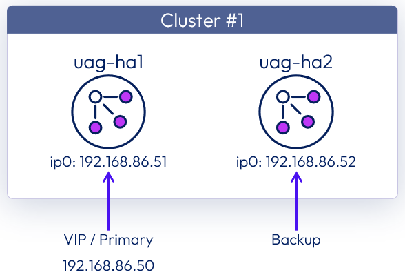
Figure 2: Unified Access Gateway cluster logical overview
Create the INI files
For this exercise, the following sample INI files are provided for the two UAG appliances that you will deploy.
- Copy the text given below for uag-ha1.ini into a text editor (for example notepad) and save it as INI file, uag-ha1.ini.
- Repeat this using the uag-ha2.ini section, creating a second INI file, uag-ha2.ini
- Copy the two INI files to the deployment machine. These should go into the same folder where you extracted the Unified Access Gateway PowerShell scripts as outlined in Prerequisites.
Note: You will need to modify some values in your version of the INI files, such as IP addresses and domain names, to match your environment.
The samples provide below configures the Horizon edge service in the deployed UAG appliances. If you are proficient in UAG deployment using PowerShell INI files, feel free to substitute in your own versions. If you do that, ensure that your INI files contain the necessary high availability section and settings.
uag-ha1.ini
[General]
name=uag-ha1
uagName=uag-ha1.eucmobility.com
adminPasswordExpirationDays=365

allowedHostHeaderValues=horizon.eucmobility.com,uag-ha1.eucmobility.com
source=C:\UAG-deploy\euc-unified-access-gateway-24.12.0.0-12815712361_OVF10.ova
target=vi://administrator@vsphere.local:PASSWORD@192.168.2.16/Dublin/host/AMD-7002/
folder=UAG

ds=esx3ssd0
diskMode=thin

ipMode=STATICV4
netInternet=Home
netManagementNetwork=Lab
netBackendNetwork=Lab
defaultGateway=192.168.86.1

deploymentOption=twonic
ip0=192.168.86.51
netmask0=255.255.255.0
ip1=192.168.2.51
netmask1=255.255.255.0
#routes0=192.168.1.0/24 192.168.0.1,192.168.2.0/24 192.168.0.2
#routes1=192.168.3.0/24 192.168.0.1,192.168.4.0/24 192.168.0.2
dns=192.168.2.10 192.168.2.11

honorCipherOrder=true
sessionTimeout=39600000

[HighAvailability]
groupID=50
virtualIPAddress=192.168.86.50

[SSLCert]
pemCerts=S:\HomeLab\Certificates\Current\eucmobility-com-chain.pem
pemPrivKey=S:\HomeLab\Certificates\Current\private.key

[SSLCertAdmin]
pemCerts=S:\HomeLab\Certificates\Current\eucmobility-com-chain.pem
pemPrivKey=S:\HomeLab\Certificates\Current\private.key

[Horizon]
proxyDestinationUrl=https://s1-hcs1.eucmobility.com
#hostEntry1=s1-hcs1.eucmobility.com

tunnelExternalUrl=https://horizon.eucmobility.com:443
blastExternalUrl=https://horizon.eucmobility.com:443
pcoipExternalUrl=46.7.178.76:4172
pcoipDisableLegacyCertificate=true
uag-ha2.ini
[General]
name=uag-ha2
uagName=uag-ha2.eucmobility.com
adminPasswordExpirationDays=365

allowedHostHeaderValues=horizon.eucmobility.com,uag-ha2.eucmobility.com
source=C:\UAG-deploy\euc-unified-access-gateway-24.12.0.0-12815712361_OVF10.ova
target=vi://administrator@vsphere.local:PASSWORD@192.168.2.16/Dublin/host/AMD-7002/
folder=UAG

ds=esx3ssd1
diskMode=thin

ipMode=STATICV4
netInternet=Home
netManagementNetwork=Lab
netBackendNetwork=Lab
defaultGateway=192.168.86.1

deploymentOption=twonic
ip0=192.168.86.52
netmask0=255.255.255.0
ip1=192.168.2.52
netmask1=255.255.255.0
#routes0=192.168.1.0/24 192.168.0.1,192.168.2.0/24 192.168.0.2
#routes1=192.168.3.0/24 192.168.0.1,192.168.4.0/24 192.168.0.2
dns=192.168.2.10 192.168.2.11

honorCipherOrder=true
sessionTimeout=39600000

[HighAvailability]
groupID=50
virtualIPAddress=192.168.86.50

[SSLCert]
pemCerts=S:\HomeLab\Certificates\Current\eucmobility-com-chain.pem
pemPrivKey=S:\HomeLab\Certificates\Current\private.key

[SSLCertAdmin]
pemCerts=S:\HomeLab\Certificates\Current\eucmobility-com-chain.pem
pemPrivKey=S:\HomeLab\Certificates\Current\private.key

[Horizon]
proxyDestinationUrl=https://s1-hcs2.eucmobility.com
#hostEntry1=s1-hcs2.eucmobility.com

tunnelExternalUrl=https://horizon.eucmobility.com:443
blastExternalUrl=https://horizon.eucmobility.com:443
pcoipExternalUrl=46.7.178.76:4172
pcoipDisableLegacyCertificate=true
Editing INI files
You will need to modify values such as IP addresses and domain names to match your environment.
- Navigate to your Unified Access Gateway INI files.
- In this example, the INI files are located in C:\UAG-deploy
- Open the INI files, for each of the UAG instances with notepad.

Review the IP address assigned to each appliance
Review the IP address that will be assigned to the external network interface (ip0) for each appliance by reviewing the INI files.
Note that distinct ip0 and ip1 addresses are used in each configuration file.
- ip0 is the external network interface (external traffic)
- ip1 is the internal interface (backend and management)
High availability settings in INI files
Each INI file that you created using the sample settings in this guide includes a section for the high availability settings.
[HighAvailability]
groupID=50
virtualIPAddress=192.168.86.50
In this configuration, all the incoming traffic on 192.168.86.50 will be balanced by the cluster of Unified Access Gateway appliances on Group ID 50.
Review the values in this section and change them as appropriate for your environment.
Note:
Deploying the Unified Access Gateway appliances
After you have reviewed the INI files for both Unified Access Gateway deployments, run the uagdeploy.ps1 PowerShell script to deploy each appliance.
Because you are deploying two appliances, you will run the script twice, passing the corresponding INI file for each deployment.
- On the deployment machine, open PowerShell.
- Navigate to the folder containing your INI files.
Your deployment machine should have the following files in a folder.
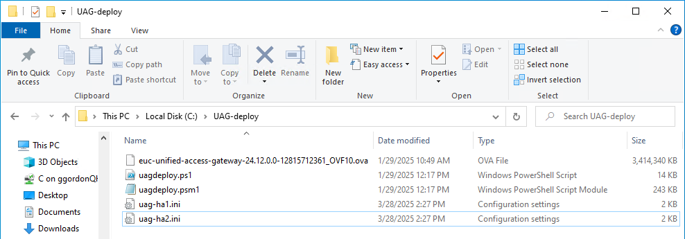
Figure 3: PowerShell script and INI files
Deploy the first appliance (uag-ha1)
Deploy the first UAG appliance, called uag-ha1, passing the uag-ha1.ini file as a parameter.
- Enter the following command in the PowerShell console.
.\uagdeploy.ps1 .\uag-ha1.ini [PASSWORD] [PASSWORD] false false yes
- The first [PASSWORD] is the root password for the Unified Access Gateway appliance.
- The second [PASSWORD] is the admin password for the REST API management access.
- The first false is to NOT skip the validation of signature and certificate.
- The second false is to NOT skip SSL verification for the vSphere connection.
- The yes is to join the CEIP program.
- After you run the script, depending on what settings you defined in the INI file you may be prompted for some input.
- If using certificate files for SSLcert or SSLcertAdmin that are protected with a password.
- A password for the vCenter user
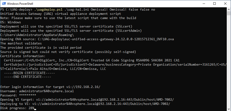
Figure 4: UAG appliance deployment progressing
The deployment starts and you can follow the progress in the same window or on your vSphere Web Client.
Confirm that the PowerShell script deployment completes
Follow the UAG appliance deployment in the PowerShell console.
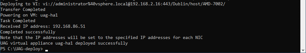
Figure 5: UAG deployment successfully completed
After successfully finalizing the deployment, the script automatically powers on the uag-ha1 VM.
The Received IP address presented by the script log may be a temporary IP. The final IPs for NIC 1 and NIC2 are assigned to the Unified Access Gateway appliance during the first boot.
Return to the vSphere Web Client to validate the deployment.
Deploy second appliance (uag-ha2)
Now deploy the second UAG appliance, called uag-ha2, passing the uag-ha2.ini file as a parameter.
- Enter the following command in the PowerShell console.
.\uagdeploy.ps1 .\uag-ha2.ini [PASSWORD] [PASSWORD] false false yes
- The first [PASSWORD] is the root password for the Unified Access Gateway appliance.
- The second [PASSWORD] is the admin password for the REST API management access.
- The first false is to NOT skip the validation of signature and certificate.
- The second false is to NOT skip SSL verification for the vSphere connection.
- The yes is to join the CEIP program.
- After you run the script, depending on what settings you defined in the INI file you may be prompted for some input.
- If using certificate files protected with a password.
- A password for the vCenter user
The deployment starts, and you can follow the progress in the same window or on your vSphere Web Client.
Review deployment
When you have deployed both UAG appliances and the PowerShell consoles show that the have successfully deployed and powered on, you should check that all VMs have been properly created and that the high availability settings are correct.
Review the appliances in the vSphere client
Use the vSphere Web client to review the network setting of the two UAG appliances.
- Click VM and Templates.
- Click uag-ha1.
- Click View all 3 IP addresses. Note the IP addresses displayed for the VM.
- Repeat steps #2 and #3 for uag-ha2. The IP addresses for this appliance should differ from uag-ha1.
Note: If the Unified Access Gateway appliance does not finalize the configuration during the first startup, you receive an error message from vSphere Web Client. If that happens, wait for the appliance to finalize, and refresh the entire browser.
Validate virtual IP address on the first appliance (uag-ha1)
Using the vSphere Web Client, validate the assignment of the additional virtual IP address to the primary appliance.
- Click VM and Templates.
- Select the uag-ha1 VM.
- In the Virtual Machine Details pane, click AND 1 MORE to show all the IP addresses configured for this VM.
- The virtual IP address 192.168.86.50 was assigned to the uag-ha1 VM, the primary appliance.
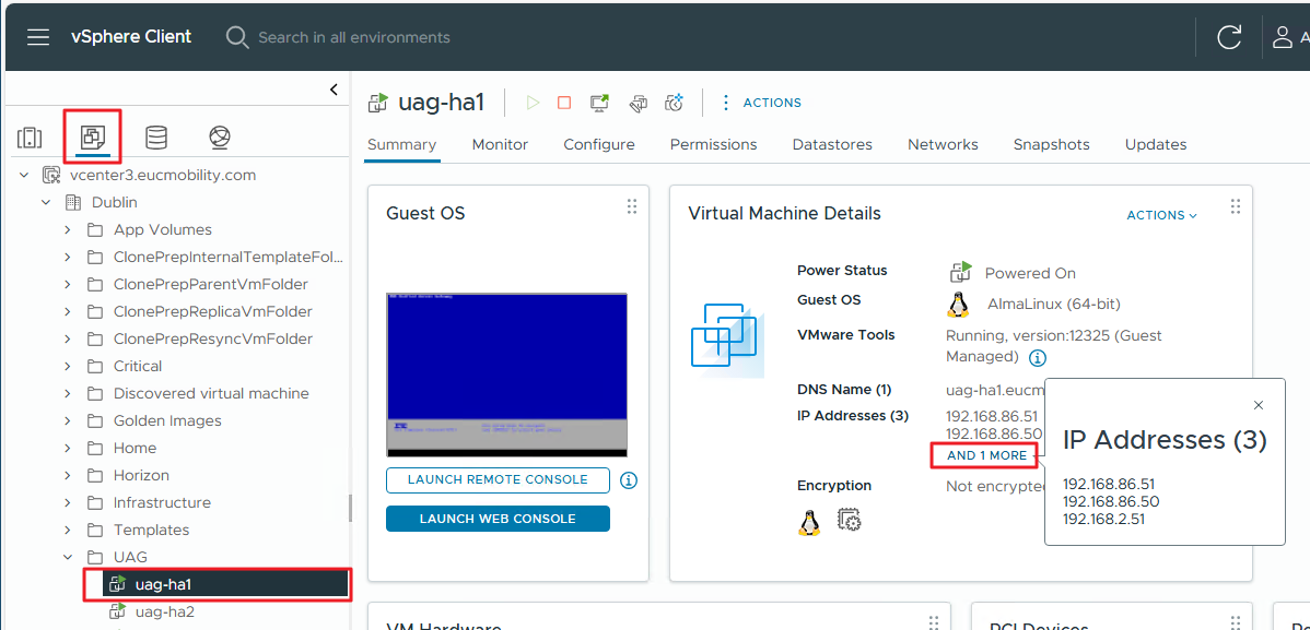
Figure 6: Validate IP addresses and the virtual IP address on the first appliance
Note: You may need to refresh the page to see the IP addresses update properly.
Perform the same steps to view the IP addresses of the uag-ha2 VM. Notice that it only has two IP addresses, as this appliance is currently the backup appliance in the high availability cluster.
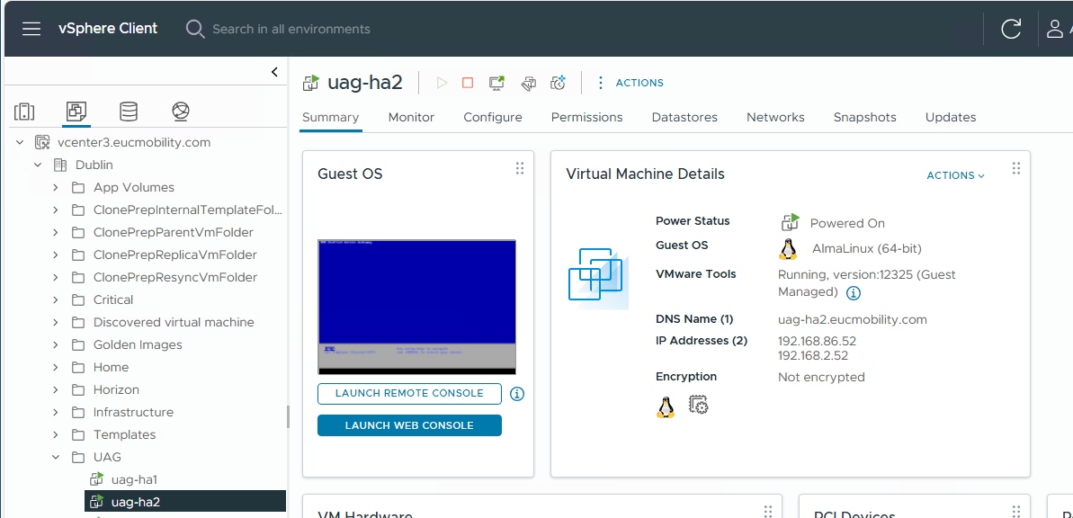
Figure 7: Check IP addresses on second appliance
Log into the UAG administration consoles
Log in to the Unified Access Gateway administration consoles.
- Open a new browser tab.
- Navigate to the DNS name or the IP address of the internal network interface of the first appliance.
- Enter the admin credentials
- The username is admin.
- Enter the password (you specified this when deploying the UAG appliance).
- Click Sign In.
- A successful login redirects you to the following screen on both appliances, where you can import settings or manually configure the Unified Access Gateway appliance individually.
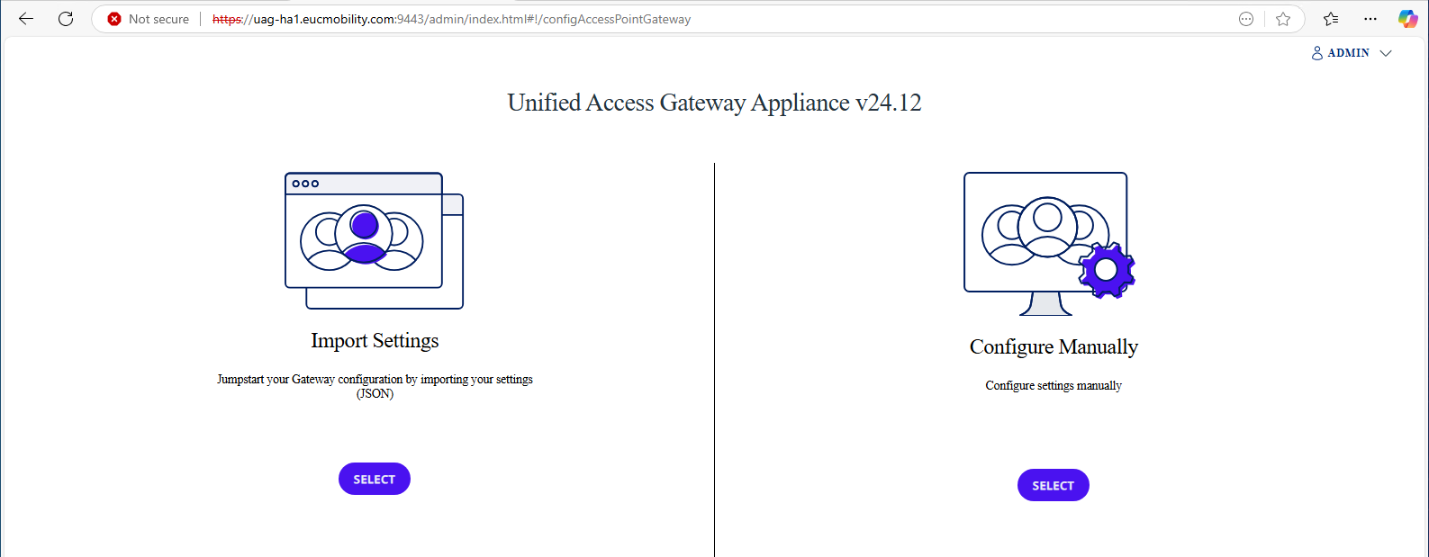
Figure 8: Select Configure Manually in the UAG admin console
- Under the Configure Manually option, click Select.
- Repeat steps 1 to 5 for the second UAG appliance, opening a new tab and login to the admin console of uag-ha2.
Check high availability settings
In the UAG administration console, you can check what the current high availability settings, and if necessary, edit the values.
- On the uag-ha1 admin console, view the value for the High Availability Settings.
- When high availability is configured correctly this should indicate either Primary or Backup. As uag-ha1 was the first UAG deployed, it should hold the Primary role and hosts the virtual IP address for the cluster.
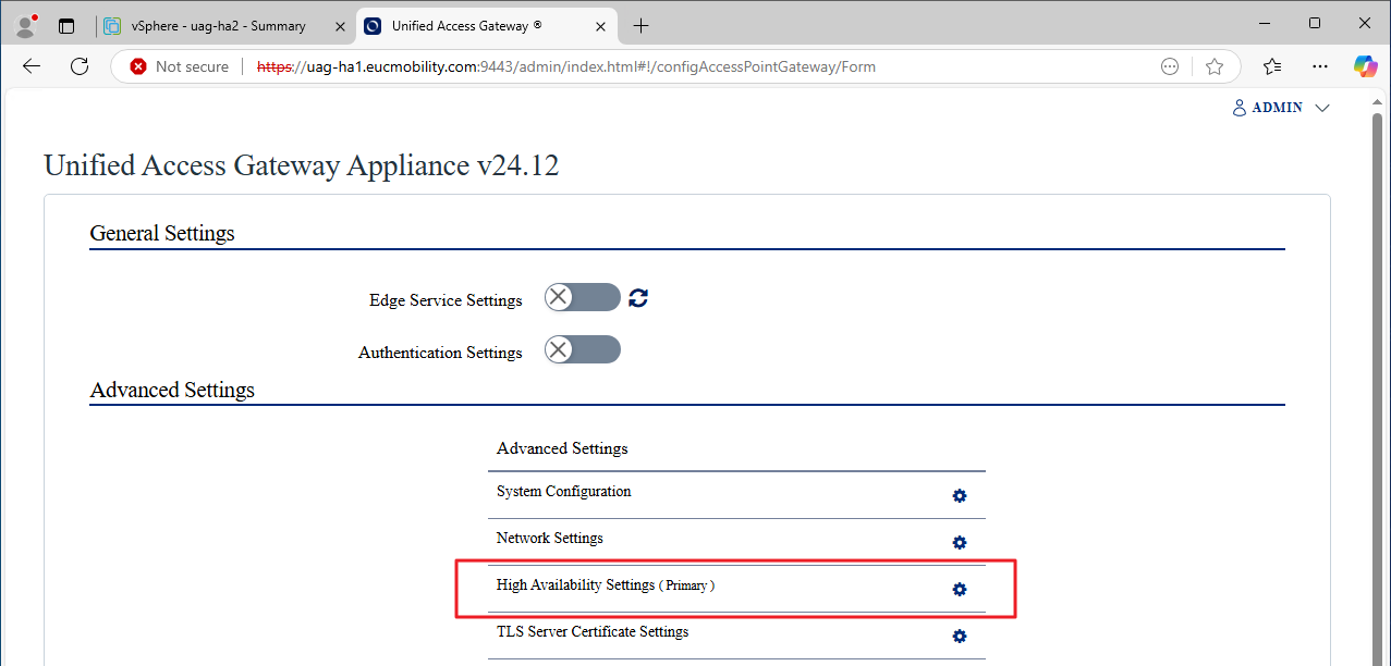
Figure 9: Check the high availability status
- Click the High Availability Settings gear icon to view the current values and optionally edit them if needed.
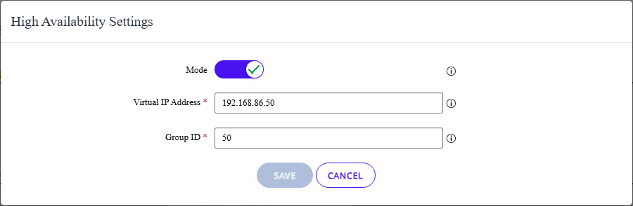
Figure 10: View and, optionally, edit the high availability settings
![]()
![]() If you save the configuration, Unified Access Gateway broadcasts a signal on the Virtual IP subnet looking for other appliances on the same Group ID. During that time, the high availability state shows as Processing.
If you save the configuration, Unified Access Gateway broadcasts a signal on the Virtual IP subnet looking for other appliances on the same Group ID. During that time, the high availability state shows as Processing.
In the case where no other appliances are found using that GroupID, uag-ha1 becomes the primary controller and the high availability state on the administration console switches to Primary as shown in the screenshot.
Note: You may need to refresh the Unified Access Gateway admin console after a few minutes to see the Processing status update to Primary.
Testing high availability
After you have completed the Unified Access Gateway high availability component configuration, you can now test the failover of the virtual IP address.
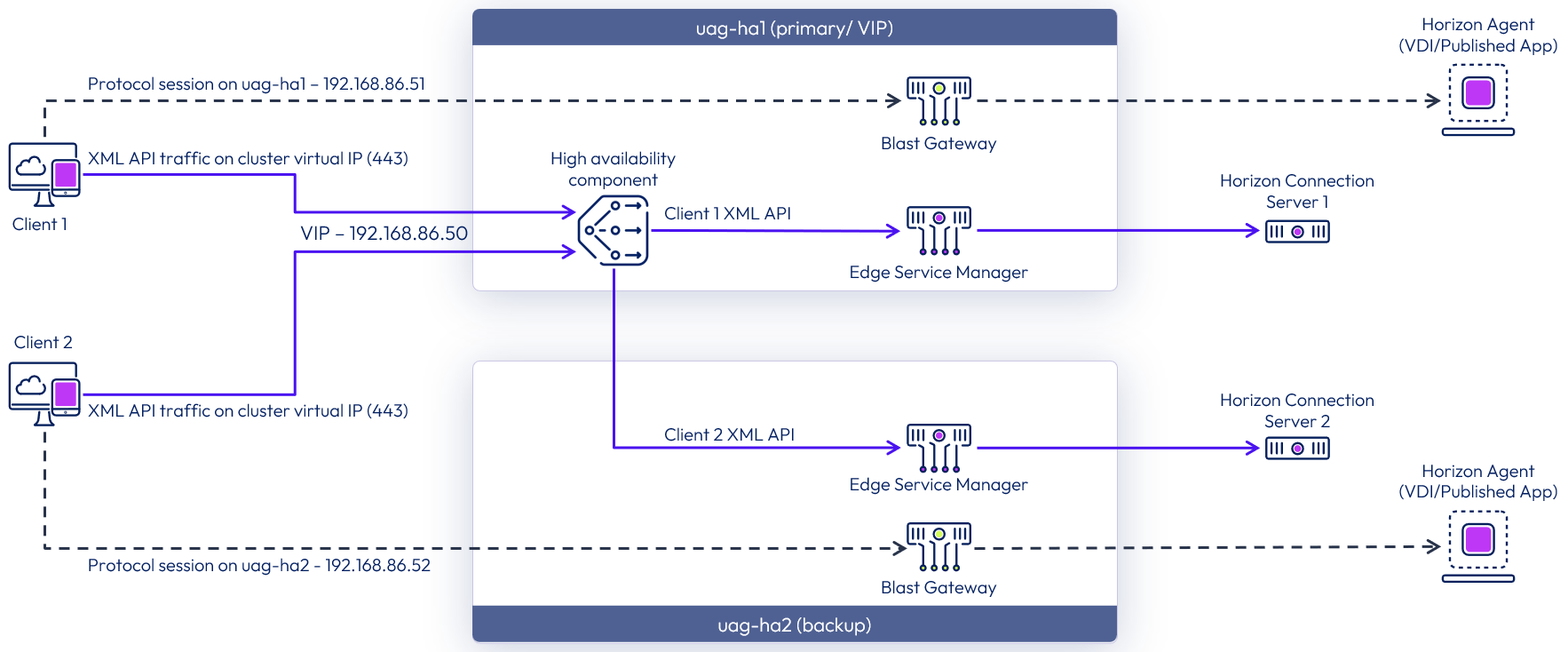
Figure 11: High availability logical architecture for Horizon Edge Service
Note: the diagram above shows the traffic flow in a high availability cluster with the Horizon Edge Service. For diagrams showing other edge services, see the High Availability section of the Unified Access Gateway Architecture guide.
For external sessions, you will need to configure your firewall or NAT device to publish external IP addresses and route traffic to the UAG appliances. Review the high availability settings section of the documentation for guidance on number of external IP addresses (usually 1 or N+1) required for the type of edge service being delivered by UAG.
Power off the first appliance (uag-ha1)
Return to the vSphere Web Client and Power Off the uag-ha1 VM.
- Click VM and Templates.
- Click uag-ha1 VM.
- Click ACTIONS.
- Hover over the Power option.
- Click Hard stop.
- Click Yes to confirm the Hard stop action for uag-ha1.
Wait for the uag-ha1 complete shutdown. This triggers the backup Unified Access Gateway appliance in the cluster (uag-ha2) to be promoted to the primary appliance.
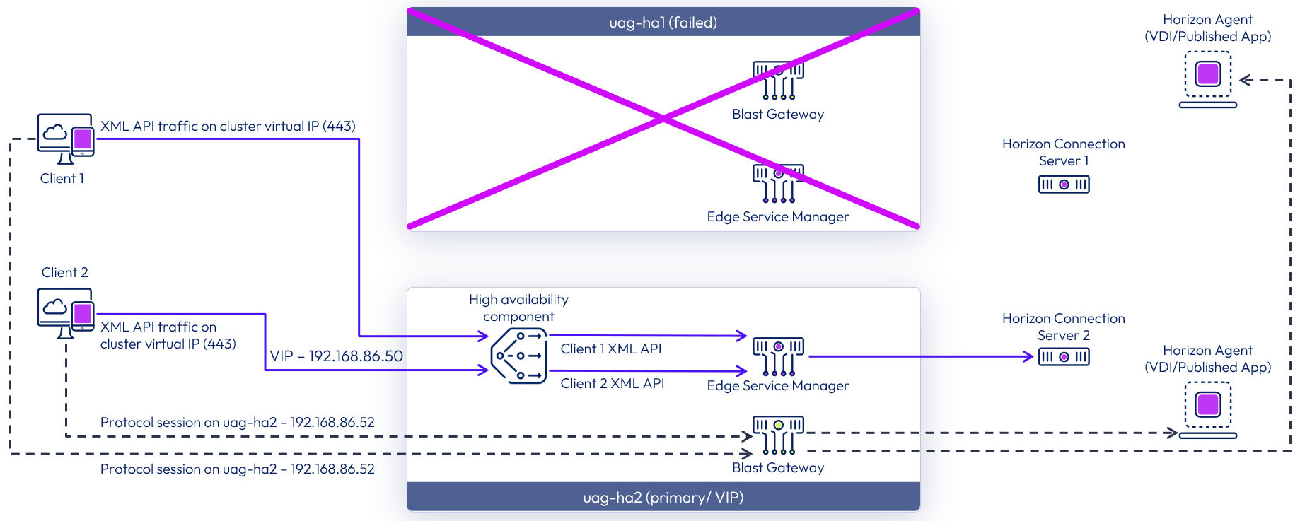
Figure 12: Failover of high availability with the Horizon Edge Service
Validate second appliance high availability status (uag-ha2)
- In your browser, return to the uag-ha2 console administration tab.
- uag-HA2 is now set as the Primary appliance, and the virtual IP address is assigned to it.
Note: If the High Availability Settings do not show uag-ha2 as the primary appliance, refresh the page.
Validate virtual IP address on the second virtual machine (uag-ha2)
Return to the vSphere Web Client to validate the assignment of the additional virtual IP address to the primary appliance.
- Click VM and Templates.
- Select uag-ha2 VM.
- In the Virtual Machine Details pane, click AND 1 MORE to show all the IP addresses configured for this VM.
- The Virtual IP address 192.168.86.50 is now assigned to the uag-ha2, the primary appliance.
Note: You may need to refresh the page to see the IP addresses update properly.
This confirms that when the primary Unified Access Gateway appliance was taken offline, the backup Unified Access Gateway appliance was promoted to primary and assigned the 192.168.86.50 virtual IP.
Summary and additional resources
In these exercises, you have learned how to:
- Deploy the Unified Access Gateway with a two NIC configuration using PowerShell script for a high availability scenario
- Configure high availability on Unified Access Gateway with settings in the PowerShell INI files.
- Perform tests on a pair of Unified Access Gateway appliances and confirm their high availability status
Additional resources
For more information about Workspace ONE, explore the Workspace ONE product page on Tech Zone.
Additionally, you can check out the Omnissa Reference Architecture which provides a framework and guidance for architecting an integrated digital workspace using Omnissa Workspace ONE and Omnissa Horizon.
For additional documentation, be sure to check:
- Unified Access Gateway Architecture
- Unified Access Gateway Technical Product Page
- Unified Access Gateway high availability documentation
Changelog
The following updates were made to this guide:
| Date | Description of Changes |
| 2025/06/27 | Added text on the need to configure the firewall or NAT with external IP addresses. |
| 2025/03/31 | Extensively rewritten and reorganized. Updated with content to cover configuring HA with INI settings. Removed the manual configuration of HA. Updated screenshots for Unified Access Gateway version 2412 Added logical diagrams illustrating what is being deployed. |
| 2024/09/20 | Update links. |
| 2019/03/31 | Guide was published. |
About the author and contributors
This tutorial was rewritten and updated by:
- Graeme Gordon, Senior Staff Architect
This initial version was written by:
- Andreano Lanusse, Alumni
Feedback
Your feedback is valuable.
To comment on this paper, either use the feedback button or contact us at tech_content_feedback@omnissa.com.